Product Description
Product Description
custom aluminum metal pinion reduction helical transmission sector Toothed Wheel Super Gear
| Item | Customized machined machining gears | |
| Process | CNC machining,CNC milling, cnc lathe machining | |
| material | steel, stainless steel, carbon steel,brass,C360 brass copper, aluminum 7075,7068 brass,C360 brass copper, aluminum Nylon, PA66, NYLON , ABS, PP,PC,PE,POM,PVC,PU,TPR,TPE,TPU,PA,PET,HDPE,PMMA etc | |
| Quality Control | ISO9001 and ISO14001 | |
| Dimension bore tolerances | -/+0.01mm | |
| Quality standard | AGMA, JIS, DIN | |
| Surface treatment | Blackening, plated, anodizing, hard anodizing etc | |
| Gear hardness | 30 to 60 H.R.C | |
| Size/Color | Gears and parts dimensions are according to drawings from customer, and colors are customized | |
| Surface treatment | Polished or matte surface, painting, texture, vacuum aluminizing and can be stamped with logo etc. | |
| Dimensions Tolerance | ±0.01mm or more precise | |
| Samples confirmation and approval | samples shipped for confirmation and shipping cost paid by customers | |
| Package | Inner clear plastic bag/outside carton/wooden pallets/ or any other special package as per customer’s requirements. | |
| Delivery Time | Total takes 2~~8weeks usually | |
| Shipping |
Usual FEDEX, UPS, DHL, TNT, EMS or base on customer’s requirement. |
Production management:
1. The workers are trained to inspect the gears and notice any defect in production in time.
2. QC will check 1pcs every 100pcs in CNC machining, and gears will meet all dimension tolerances.
3. Gears will be inspected at every step, and gears will be inspected before shipment, and all inspection records will be kept in our factory for 3 years.
4. Our sales will send you pictures at every gears production steps, and you will know the detailed production status, and you can notice any possibility of mistake, for our sales, QC and workers are keeping close watch on all production.
5. You will feel us working very carefully to assure the quality and easy to work with,
6. we cherish every inquiry, every opportunity to make gears and parts and cherish every customer.
QUALITY CONTROL PROCESS:
1) Inspecting the raw material –IQC)
2) Checking the details before the production line operated
3) Have full inspection and routing inspection during mass production—In process quality control (IPQC)
4) Checking the gears after production finished—- (FQC)
5) Checking the gears after they are finished—–Outgoing quality control (OQC)
Service:
1. Molds designs as per customers’ gears drawing;
2. Submitting molds drawings to customers to review and confirm before mols production.
3. Providing samples with whole dimensions and cosmetic inspection report, material certification to customers.
4. Providing inspection report of important dimensions and cosmetic in batches parts.
Packing and shipment:
1. Gears are well and carefully packed in PP bags in CTNS, strong enough for express shipping, air shipment or sea shipment.
2. Air shipment, sea shipment or shipment by DHL, UPS, FedEx or TNT are availabe.
3. Trade terms: EXW, FOB HangZhou, or CIF
4. All shippings will be carefully arranged and will reach your places fast and safely.
FAQ
Q1: How to guarantee the Quality of gears and parts?
We are ISO 9001:2008 certified factory and we have the integrated system for industrial parts quality control. We have IQC (incoming quality control),
IPQCS (in process quality control section), FQC (final quality control) and OQC (out-going quality control) to control each process of industrial parts prodution.
Q2: What are the Advantage of your gears and parts?
Our advantage is the competitive and reasonable prices, fast delivery and high quality. Our eployees are responsible-oriented, friendly-oriented,and dilient-oriented.
Our industrial parts products are featured by strict tolerance, smooth finish and long-life performance.
Q3: what are our machining equipments?
Our machining equipments include plasticn injection machinies, CNC milling machines, CNC turning machines, stamping machines, hobbing machines, automatic lathe machines, tapping machines, grinding machines, cutting machines and so on.
Q4: What shipping ways do you use?
Generally, we will use UPS DHL or FEDEX and sea shipping
5: What materials can you process?
For plastic injection gears and parts, the materials are Nylon, PA66, NYLON with 30% glass fibre, ABS, PP,PC,PE,POM,PVC,PU,TPR,TPE,TPU,PA,PET,HDPE,PMMA etc.
For metal and machining gears and parts, the materials are brass, bronze, copper, stainless steel, steel, aluminum, titanium plastic etc.
Q6: How long is the Delivery for Your gears and parts?
Generally , it will take us 15 working days for injection or machining, and we will try to shorten our lead time.
/* January 22, 2571 19:08:37 */!function(){function s(e,r){var a,o={};try{e&&e.split(“,”).forEach(function(e,t){e&&(a=e.match(/(.*?):(.*)$/))&&1
| Application: | Motor, Electric Cars, Machinery, Toy, Agricultural Machinery, Car |
|---|---|
| Hardness: | Hardened Tooth Surface |
| Gear Position: | External Gear |
| Manufacturing Method: | Cut Gear |
| Toothed Portion Shape: | Curved Gear |
| Material: | Stainless Steel |
| Samples: |
US$ 10/Piece
1 Piece(Min.Order) | |
|---|
| Customization: |
Available
| Customized Request |
|---|

How does a helical gear impact the overall efficiency of a system?
A helical gear has a significant impact on the overall efficiency of a system. Due to their unique design and characteristics, helical gears offer several advantages that contribute to improved efficiency. Here’s a detailed explanation of how a helical gear impacts the overall efficiency of a system:
- Power Transmission: Helical gears provide efficient power transmission due to their inclined tooth design. The helical teeth engage gradually, resulting in a smooth transfer of torque between the gears. This gradual engagement reduces impact and shock loads, minimizing energy losses and improving overall efficiency.
- Load Distribution: The helical tooth profile allows for increased contact area between the gear teeth compared to other gear types. This larger contact area results in improved load distribution across the gear teeth. By distributing the load more evenly, helical gears can handle higher loads without excessive wear and reduce the risk of tooth failure, leading to increased efficiency and reliability.
- Noise and Vibration Reduction: Helical gears operate with less noise and vibration compared to other gear types, such as spur gears. The inclined tooth profile of helical gears helps to minimize gear meshing noise and vibration by distributing the forces along the gear teeth over a larger contact area. Reduced noise and vibration levels contribute to a quieter and smoother operation, indicating lower energy losses and improved overall efficiency.
- Higher Gear Ratios: Helical gears can achieve higher gear ratios compared to other gear types. This capability allows for more precise speed control and torque conversion in various applications. By providing the desired gear ratios, helical gears enable the system to operate at optimal speeds and torque levels, maximizing efficiency and performance.
- Efficient Lubrication: The helical gear design allows for effective lubrication of the gear teeth. The continuous sliding action between the helical teeth assists in distributing the lubricant evenly along the gear contact surfaces. Proper lubrication reduces friction and wear, minimizing energy losses and enhancing the overall efficiency of the gear system.
- Compact Design: Helical gears have a compact design that allows for efficient use of space within a system. The inclined tooth profile enables multiple gear sets to be positioned on parallel or intersecting shafts, facilitating compact gear arrangements. This compactness reduces the overall size and weight of the system while maintaining high efficiency.
- High Precision: Helical gears offer excellent positional accuracy and repeatability. The helical tooth profile ensures precise and consistent gear meshing, resulting in accurate motion control and minimal backlash. This precision contributes to efficient operation, especially in applications requiring precise positioning and synchronization of components.
- Wear Resistance: Helical gears exhibit good wear resistance due to the larger contact area and gradual tooth engagement. The inclined tooth profile helps distribute the load, reducing localized wear and extending the gear’s service life. Reduced wear translates to sustained gear efficiency over time, minimizing the need for frequent replacements and maintenance.
Overall, the design characteristics of helical gears, including smooth power transmission, load distribution, noise reduction, higher gear ratios, efficient lubrication, compactness, precision, and wear resistance, collectively contribute to improved system efficiency. By choosing helical gears appropriately for a given application, engineers can enhance the overall performance, reliability, and energy efficiency of the system.
How do you address noise and vibration issues in a helical gear system?
In a helical gear system, addressing noise and vibration issues is crucial to ensure smooth and quiet operation, minimize component wear, and enhance overall system performance. Here’s a detailed explanation of how to address noise and vibration issues in a helical gear system:
- Proper Gear Design: The design of the helical gears can significantly impact noise and vibration levels. Design considerations such as the helix angle, tooth profile modification, and gear tooth contact pattern optimization can help minimize gear noise and vibration. A well-designed gear system with proper tooth geometry and accurate alignment reduces the likelihood of gear meshing irregularities that contribute to noise and vibration.
- Precision Manufacturing: High-quality manufacturing processes are essential to minimize noise and vibration in helical gear systems. Precise gear cutting techniques, such as hobbing or grinding, ensure accurate tooth profiles, which help reduce gear meshing deviations and associated noise. Additionally, maintaining tight manufacturing tolerances and surface finishes on gear components can help minimize vibration caused by irregularities or imperfections.
- Alignment and Assembly: Proper alignment and assembly of the helical gears are critical to minimize noise and vibration. Ensuring precise alignment of the gear shafts and gear meshing is essential to achieve optimal contact between the gear teeth. The use of alignment tools, such as dial indicators or laser alignment systems, can aid in achieving accurate alignment. Additionally, proper assembly techniques, including appropriate gear backlash and preload adjustment, can help minimize noise and vibration by optimizing gear meshing conditions.
- Optimal Lubrication: Proper lubrication is vital for reducing noise and vibration in a helical gear system. Adequate lubrication creates a thin film between the gear teeth, minimizing friction and wear. The lubricant also helps to dampen vibrations and dissipate heat generated during gear operation. Using the correct lubricant type, viscosity, and maintaining proper lubricant levels are essential for noise and vibration control.
- Stiffness of Gearbox Housing: The stiffness and rigidity of the gearbox housing influence noise and vibration levels in a helical gear system. A robust and well-designed housing structure helps to minimize the transmission of vibrations from the gears to the surrounding environment. It is important to ensure that the gearbox housing is adequately braced and supported to reduce resonances and vibrations that can contribute to noise.
- Vibration Damping: Implementing vibration damping techniques can help mitigate noise and vibration in a helical gear system. This can include the use of vibration-absorbing materials, such as elastomers or damping pads, at appropriate locations within the gear system. These materials help absorb and dissipate vibrations, reducing noise transmission and minimizing gear system resonance.
- Condition Monitoring and Maintenance: Regular condition monitoring and maintenance practices are essential for identifying and addressing noise and vibration issues in a helical gear system. Periodic inspections, including vibration analysis, can detect any abnormal vibration patterns or wear indications. Timely maintenance, such as addressing misalignment, worn components, or inadequate lubrication, can prevent further deterioration and reduce noise and vibration levels.
By implementing these measures, engineers can effectively address noise and vibration issues in a helical gear system, resulting in quieter operation, reduced component wear, and improved overall system performance.

How do you choose the right size helical gear for your application?
Choosing the right size helical gear for your application involves considering several factors to ensure optimal performance and reliability. Here’s a detailed explanation of the steps involved in selecting the right size helical gear:
- Determine the Application Requirements: Start by understanding the specific requirements of your application. Consider factors such as the desired speed ratio, torque requirements, power transmission capacity, operating conditions (including temperature, lubrication, and environment), and any special considerations unique to your application.
- Calculate the Gear Parameters: Based on the application requirements, calculate the necessary gear parameters. These parameters include the pitch diameter, number of teeth, module or pitch, pressure angle, helix angle, face width, and center distance. These calculations can be performed using gear design formulas or software tools specifically designed for gear selection.
- Consider Load and Strength: Evaluate the load conditions that the helical gear will experience. Take into account factors such as the transmitted torque, radial loads, axial loads, and dynamic forces. Ensure that the selected gear can withstand the anticipated loads and provide sufficient strength and durability. Consider factors such as gear material, heat treatment, and tooth geometry to ensure adequate load-carrying capacity and resistance to wear and fatigue.
- Check Gear Meshing and Alignment: Proper gear meshing and alignment are crucial for smooth operation and efficient power transmission. Ensure that the selected gear size and tooth profile allow for proper meshing with the mating gear. Consider factors such as backlash, tooth contact pattern, and alignment tolerances to minimize noise, vibration, and wear. Proper alignment of shafts and bearings is also important for optimal gear performance.
- Consider Space Limitations: Evaluate the available space in your application for gear installation. Consider factors such as the gear diameter, length, and clearance requirements. Ensure that the selected gear size can fit within the available space without interfering with other components or causing installation challenges.
- Consult Manufacturer’s Guidelines: Refer to the manufacturer’s guidelines, catalogs, and technical documentation for the specific type and brand of helical gear you are considering. Manufacturers often provide recommendations, selection charts, and engineering support to assist in choosing the right size gear for different applications. It’s beneficial to leverage their expertise and knowledge.
- Consider Cost and Availability: Evaluate the cost and availability of the selected helical gear. Consider factors such as the gear’s price, lead time, availability of spare parts, and any additional costs associated with installation or maintenance. Balance your requirements with the available budget and ensure that the chosen gear offers a cost-effective solution without compromising performance or quality.
By following these steps and considering the application requirements, load conditions, gear parameters, meshing characteristics, space limitations, manufacturer’s guidelines, and cost factors, you can choose the right size helical gear that meets your specific application needs.
It’s important to note that gear selection can be a complex process, and it may be beneficial to consult with an experienced engineer or gear specialist to ensure an accurate and optimized gear sizing for your specific application.


editor by Dream 2024-05-09
China best High Performance Helical Gear for Automotive Rear Axle Gearbox for Robotic with ISO9001 bevel gear set
Product Description
Product Description
Product Parameters
| product | High Performance Helical Gear for Automotive Rear Axle Gearbox for Robotic With ISO9001 |
| material | stainless steel , iron , aluminum ,bronze ,carbon steel ,brass etc . |
| size | ISO standard ,customer requirements |
| BORE | Finished bore, Pilot Bore, Special request |
| surface treatment | Carburizing and Quenching,Tempering ,Tooth suface high quenching Hardening,Tempering |
| Processing Method | Molding, Shaving, Hobbing, Drilling, Tapping, Reaming, Manual Chamfering, Grinding etc |
| Heat Treatment | Quenching & Tempering, Carburizing & Quenching, High-frequency Hardening, Carbonitriding…… |
| Package | Wooden Case/Container and pallet, or made-to-order |
| Certificate | ISO9001 ,SGS |
| Machining Process | Gear Hobbing, Gear Milling, Gear Shaping, Gear Broaching, Gear Shaving, Gear Grinding and Gear Lapping |
| Applications | Toy, Automotive, instrument, electrical equipment, household appliances, furniture, mechanical equipment,daily living equipment, electronic sports equipment, , sanitation machinery, market/ hotel equipment supplies, etc. |
| Testing Equipment | Rockwell hardness tester 500RA, Double mesh instrument HD-200B & 3102,Gear measurement center instrument CNC3906T and other High precision detection equipments |
workshop & equipment
Production process
Certifications
Our Advantages
1 . Prioritized Quality
2 .Integrity-based Management
3 .Service Orientation
4 .150+ advanced equipment
5 .10000+ square meter factory area
6 .200+ outstanding employees
7 .90% employees have more than 10 year- working experience in our factory
8 .36 technical staff
9 .certificate ISO 9001 , SGS
10 . Customization support
11 .Excellent after-sales service
shipping
sample orders delivery time:
10-15 working days as usual
15-20 working days in busy season
large order leading time :
20-30 working days as usual
30-40 working days in busy season
FAQ
1. why should you buy products from us not from other suppliers?
We are a 32 year-experience manufacturer on making the gear, specializing in manufacturing varieties of gears, such as helical gear ,bevel gear ,spur gear and grinding gear, gear shaft, timing pulley, rack, , timing pulley and other transmission parts . There are 150+ advanced equipment ,200+ excellent employees ,and 36 technical staff . what’s more ,we have got ISO9001 and SGS certificate .
2: What are the common types of tooth profiles for synchronous belt pulleys?
A: The most common tooth profiles for synchronous belt pulleys are the trapezoidal (or T-type) and curvilinear (or HTD-type) profiles. The tooth profile determines the pitch diameter, which affects the overall ratio of the gear drive.
3 .How long is the delivery?
A: Small orders usually takes 10-15 working days,big order usually 20-35 days, depending on orders quantity and whether are standard size.
/* January 22, 2571 19:08:37 */!function(){function s(e,r){var a,o={};try{e&&e.split(“,”).forEach(function(e,t){e&&(a=e.match(/(.*?):(.*)$/))&&1
| Standard: | ANSI |
|---|---|
| Material: | Stainless Steel |
| Connection: | Welding |
| Surface Treatment: | Black Oxide |
| Head Type: | Round |
| Customization: | as Requirement |
| Samples: |
US$ 5/Piece
1 Piece(Min.Order) | |
|---|
| Customization: |
Available
| Customized Request |
|---|

What are the advantages and disadvantages of using helical gears?
Helical gears offer several advantages and disadvantages compared to other types of gears. It’s important to consider these factors when selecting the appropriate gear type for a specific application. Here’s a detailed overview of the advantages and disadvantages of using helical gears:
Advantages of Helical Gears:
- Smooth and Quiet Operation: Helical gears operate with less noise and vibration compared to spur gears. The inclined tooth profile allows for gradual tooth engagement, resulting in smooth and quiet gear meshing. This advantage makes helical gears suitable for applications that require low noise levels and improved operator comfort.
- High Load-Carrying Capacity: The inclined teeth of helical gears provide a larger contact area compared to other gear types. This increased contact area enables helical gears to handle higher loads and transmit greater torque without excessive wear or risk of tooth failure. Helical gears are known for their high load-carrying capacity, making them suitable for heavy-duty applications.
- Efficient Power Transmission: Helical gears offer efficient power transmission due to their inclined tooth design. The gradual engagement of helical teeth reduces impact and shock loads, minimizing energy losses and improving overall system efficiency. This advantage makes helical gears suitable for applications where power efficiency is critical.
- Higher Gear Ratios: Helical gears can achieve higher gear ratios compared to other gear types. This capability allows for more precise speed control and torque conversion in various applications. Helical gears are ideal for systems that require fine-tuning of rotational speed and torque output.
- Compact Design: Helical gears have a compact design that allows for efficient use of space within a system. The inclined tooth profile enables multiple gear sets to be positioned on parallel or intersecting shafts, facilitating compact gear arrangements. This advantage is particularly useful in applications with space constraints.
- Good Meshing Characteristics: Helical gears exhibit excellent meshing characteristics, including smooth gear engagement and minimal backlash. The inclined tooth profile ensures precise gear meshing, resulting in accurate motion control and reduced vibration. This advantage is desirable in applications that require precise positioning and synchronization of components.
Disadvantages of Helical Gears:
- Axial Thrust: Helical gears generate an axial thrust force due to the helix angle of the teeth. This axial thrust must be properly supported to prevent axial movement of the gear shafts. Additional thrust bearings or thrust plates may be required, adding complexity and cost to the gear system design.
- Complex Manufacturing: The manufacturing process of helical gears is more complex compared to spur gears. The inclined tooth profile requires specialized cutting tools and machinery to produce accurate helical gears. This complexity can result in higher manufacturing costs and longer lead times for custom gears.
- Efficiency Reduction at High Speeds: Helical gears may experience a reduction in efficiency at high rotational speeds. This reduction is due to an increase in axial thrust forces, which generate additional friction and energy losses. Proper lubrication and design considerations are necessary to mitigate this efficiency reduction.
- Thrust Load Sensitivity: Helical gears are sensitive to axial thrust loads. Uneven distribution of axial loads or improper alignment of gears can lead to increased wear and premature failure. Careful consideration of gear design, proper alignment, and adequate thrust load support are essential to ensure gear longevity and reliable operation.
- Limited Ratios: Although helical gears can achieve higher gear ratios compared to spur gears, their range of available gear ratios is limited compared to other gear types, such as worm gears or bevel gears. If a very high or very low gear ratio is required for a specific application, other gear types may be more suitable.
Considering these advantages and disadvantages, engineers can make informed decisions when selecting helical gears for their specific applications. By carefully evaluating the requirements and constraints of the system, they can leverage the strengths of helical gears while mitigating any potential limitations.
How do you retrofit an existing mechanical system with helical gears?
Retrofitting an existing mechanical system with helical gears involves replacing the current gear system with helical gears to improve performance, efficiency, or address specific requirements. The process requires careful planning, analysis, and implementation to ensure a successful retrofit. Here is a detailed explanation of how to retrofit an existing mechanical system with helical gears:
- Assess the Existing System: Begin by thoroughly assessing the existing mechanical system. Understand its design, operating conditions, gear specifications, and performance limitations. Identify the reasons for retrofitting, such as the need for increased load capacity, improved efficiency, noise reduction, or other specific requirements.
- Define Retrofit Objectives: Clearly define the objectives of the retrofit. Determine the specific improvements or modifications desired from the retrofit. This could include increasing torque capacity, reducing backlash, improving gear meshing characteristics, or optimizing gear ratios. Having well-defined objectives will guide the retrofitting process.
- Perform Gear Design and Analysis: Based on the defined objectives, conduct gear design and analysis to determine the appropriate helical gear configuration. Consider factors such as gear size, tooth profile, helix angle, module or diametral pitch, and gear material. Use engineering calculations, software simulations, or consult with gear design experts to ensure the selected helical gears meet the retrofit objectives and are compatible with the existing system.
- Modify Gear Housing and Mounting: In some cases, retrofitting with helical gears may require modifications to the gear housing or mounting arrangements. Ensure that the gear housing can accommodate the helical gears and provide proper alignment and support. Modify or adapt the housing as necessary to ensure a precise fit and alignment of the new gear system.
- Manufacture or Source Helical Gears: Once the gear design is finalized, manufacture or source the helical gears according to the specifications determined during the design phase. Work with experienced gear manufacturers or suppliers who can provide high-quality helical gears that meet the required specifications and performance criteria.
- Installation and Alignment: Remove the existing gears and install the helical gears in the mechanical system. Ensure proper alignment of the gears to maintain smooth operation and minimize wear. Follow recommended installation procedures and torque specifications provided by the gear manufacturer. Consider using alignment tools, such as dial indicators or laser alignment systems, to achieve precise gear alignment.
- Test and Fine-tune: After installation, conduct thorough testing of the retrofit system. Monitor performance, check for any abnormal vibrations, noise, or operating issues. Fine-tune the system as needed, making adjustments to gear meshing, lubrication, or other parameters to optimize performance and ensure the retrofit objectives are met.
- Monitor and Maintain: Once the retrofit is complete, establish a regular monitoring and maintenance schedule. Periodically inspect the helical gears for wear, perform lubrication checks, and address any maintenance requirements. Regular monitoring and maintenance will help ensure the longevity and optimal performance of the retrofit system.
Retrofitting an existing mechanical system with helical gears can significantly enhance its performance, efficiency, and reliability. However, it is essential to carefully plan and execute the retrofitting process to achieve the desired outcomes. Consulting with gear design experts and experienced professionals can provide valuable guidance and expertise throughout the retrofitting process.
What are the applications of helical gears?
Helical gears find wide-ranging applications in various mechanical systems due to their advantageous characteristics and capabilities. Here’s a detailed explanation of the applications of helical gears:
1. Power Transmission: Helical gears are commonly used for power transmission in a wide range of industries. They are employed in machinery and equipment where rotational motion needs to be transmitted between parallel shafts. Examples include gearboxes, industrial machinery, conveyors, and automotive transmissions.
2. Rotary Motion Control: Helical gears are used in applications where precise rotary motion control is required. They provide smooth and accurate motion transfer, making them suitable for applications such as robotics, precision equipment, machine tools, and positioning systems.
3. High Torque Applications: Due to their design and tooth engagement characteristics, helical gears are well-suited for high torque applications. They can efficiently transmit substantial power and handle heavy loads. This makes them suitable for heavy machinery, construction equipment, mining machinery, and marine propulsion systems.
4. Automotive Industry: Helical gears are extensively used in automotive applications. They are found in transmissions, differentials, and powertrain systems, where they facilitate smooth and efficient power transmission while reducing noise and vibration. Helical gears help achieve the desired gear ratios and torque multiplication in vehicles.
5. Machine Tools: Machine tools, such as milling machines, lathes, and gear hobbing machines, utilize helical gears for precise motion control and power transmission. Helical gears enable accurate and smooth rotation of cutting tools and workpieces, contributing to the high precision and quality of machined components.
6. Printing Industry: Helical gears are used in printing presses and other printing equipment. They facilitate the precise movement of paper and printing plates, ensuring accurate registration and high-quality printing results.
7. Textile Industry: In the textile industry, helical gears are employed in various machinery and equipment. They are used in spinning machines, weaving machines, and other textile processing equipment that require precise motion control and power transmission for efficient textile production.
8. Oil and Gas Industry: Helical gears are utilized in oil and gas equipment and machinery. They are found in pumps, compressors, drilling rigs, and other critical components where high torque transmission and reliable motion control are essential for efficient operations.
9. Power Generation: Helical gears play a crucial role in power generation systems. They are employed in wind turbines, hydroelectric generators, and other power generation equipment to transmit rotational motion from the turbine or generator shaft to the electrical generator, ensuring efficient electricity production.
10. General Machinery: Helical gears have diverse applications in general machinery across various industries. They are used in packaging equipment, food processing machinery, material handling systems, and numerous other mechanical systems that require reliable power transmission and precise motion control.
The versatility, load-carrying capacity, and smooth operation of helical gears make them suitable for numerous applications in different industries. The specific design, tooth profile, helix angle, and material selection can be tailored to meet the requirements of each application, ensuring optimal performance and longevity of the gear system.
editor by Dream 2024-05-09
China Standard Electric Car Reducer Motor Cylindrical Internal Helical Bevel Gear supplier
Product Description
Electric car reducer motor cylindrical internal helical bevel gear
Product Parameters
| product name | Factory Supplies High Precision Customized Standard Steel Spur Pinion Gear |
| material | stainless steel , iron , aluminum ,bronze ,carbon steel ,brass , nylon etc . |
| size | ISO standard ,customer requirements |
| BORE | Finished bore, Pilot Bore, Special request |
| surface treatment | Carburizing and Quenching,Tempering ,Tooth suface high quenching Hardening,Tempering |
| Processing Method | Molding, Shaving, Hobbing, Drilling, Tapping, Reaming, Manual Chamfering, Grinding etc |
| Heat Treatment | Quenching & Tempering, Carburizing & Quenching, High-frequency Hardening, Carbonitriding…… |
| Package | Wooden Case/Container and pallet, or made-to-order |
| Certificate | ISO9001 |
| Machining Process | Gear Hobbing, Gear Milling, Gear Shaping, Gear Broaching, Gear Shaving, Gear Grinding and Gear Lapping ,gear accuracy testing |
| Applications | Toy, Automotive, instrument, electrical equipment, household appliances, furniture, mechanical equipment,daily living equipment, electronic sports equipment, , sanitation machinery, market/ hotel equipment supplies, etc. |
| Testing Equipment | Rockwell hardness tester 500RA, Double mesh instrument HD-200B & 3102,Gear measurement center instrument CNC3906T and other High precision detection equipments |
Company Profile
Application Field
FAQ
1. why should you buy products from us not from other suppliers?
We are a 32 year-experience manufacturer on making the gear, specializing in manufacturing varieties of gears, such as helical gear ,bevel gear ,spur gear and grinding gear, gear shaft, timing pulley, rack, , timing pulley and other transmission parts .
2. what services can we provide?
Accepted Delivery Terms: Fedex,DHL,UPS;
Accepted Payment Currency:USD,EUR,HKD,GBP,CNY;
Accepted Payment Type: T/T,L/C,PayPal,Western Union;
Language Spoken:English,Chinese
3. how can we guarantee quality?
1 .Always a pre-production sample before mass production;
2 .Always final Inspection before shipment;
3 .We have high-precision CNC gear grinding machine, high-speed CNC gear hobbing machine, CNC gear shaping machine, CNC lathe, CNC machining center, various grinding machines, universal gear measuring instrument, heat treatment and other advanced processing equipment.
4 . We have a group of experienced technical workers, more than 90% of the workers have more than 10 years of work experience in this factory, can accurately control the manufacturing of products and customer needs. We regularly train our employees to ensure that we can produce high-precision and high-quality products that are more in line with our customers’ needs.
/* January 22, 2571 19:08:37 */!function(){function s(e,r){var a,o={};try{e&&e.split(“,”).forEach(function(e,t){e&&(a=e.match(/(.*?):(.*)$/))&&1
| Application: | Motor, Electric Cars, Motorcycle, Machinery, Marine, Toy, Agricultural Machinery, Car, Packing Machine |
|---|---|
| Hardness: | Hardened Tooth Surface |
| Gear Position: | External Gear |
| Customization: |
Available
| Customized Request |
|---|
.shipping-cost-tm .tm-status-off{background: none;padding:0;color: #1470cc}
|
Shipping Cost:
Estimated freight per unit. |
about shipping cost and estimated delivery time. |
|---|
| Payment Method: |
|
|---|---|
|
Initial Payment Full Payment |
| Currency: | US$ |
|---|
| Return&refunds: | You can apply for a refund up to 30 days after receipt of the products. |
|---|

What is the purpose of using helical gears in power transmission?
Helical gears are commonly used in power transmission systems for various purposes. Here’s a detailed explanation of the purpose and advantages of using helical gears in power transmission:
- Smooth and Efficient Power Transfer: One of the primary purposes of using helical gears in power transmission is to achieve smooth and efficient transfer of power. The inclined tooth profile of helical gears allows for gradual and continuous engagement of teeth, minimizing shock loads and ensuring a more uniform distribution of force. This results in smoother power transmission with reduced noise, vibration, and wear.
- High Torque Transmission: Helical gears are known for their high torque-carrying capacity. The inclined teeth of helical gears enable a larger tooth contact area compared to other gear types such as spur gears. This increased tooth contact area allows helical gears to transmit higher torque, making them suitable for applications that require the transfer of large amounts of power, such as in industrial machinery, automotive drivetrains, and heavy-duty equipment.
- Variable Speed Ratios: Helical gears can be designed with different numbers of teeth and varying helix angles, allowing for a wide range of speed ratios. By selecting the appropriate combination of gears, the rotational speed and torque can be adjusted to meet the requirements of the power transmission system. This flexibility in speed ratios makes helical gears versatile in applications where variable speed control is necessary.
- Reduction of Noise and Vibration: The inclined tooth profile and gradual engagement of helical gears contribute to the reduction of noise and vibration in power transmission systems. Compared to spur gears, helical gears generate less noise and vibration due to their smoother meshing characteristics and improved load distribution. This makes helical gears particularly beneficial in applications where noise reduction and smooth operation are important considerations, such as in automotive transmissions and precision equipment.
- Compact Design: Helical gears can achieve high gear ratios within a relatively compact design. The inclined teeth of helical gears allow for more teeth to be in contact at any given time, enabling a higher gear ratio compared to spur gears of the same size. This compactness is advantageous when there are space constraints or when a smaller gear mechanism is desired without sacrificing performance or torque capacity.
- High Reliability and Durability: Helical gears are designed to distribute the load over multiple teeth, resulting in improved load-carrying capacity and enhanced gear strength. The inclined tooth profile allows for a larger contact area, reducing stress concentrations and increasing the gear’s resistance to wear and fatigue. These factors contribute to the high reliability and durability of helical gears, making them suitable for demanding power transmission applications that require long service life.
In summary, the purpose of using helical gears in power transmission is to achieve smooth and efficient power transfer, high torque transmission, variable speed control, noise and vibration reduction, compact design, and high reliability. These advantages make helical gears widely used in various industries, including automotive, manufacturing, energy, and many other applications that require reliable and efficient power transmission.
How do you address thermal expansion and contraction in a helical gear system?
Addressing thermal expansion and contraction in a helical gear system is crucial to ensure proper operation and prevent potential issues such as misalignment, increased backlash, or premature wear. Thermal expansion and contraction occur when temperature changes cause the gear components to expand or contract, affecting the gear meshing and overall performance. Here is a detailed explanation of how to address thermal expansion and contraction in a helical gear system:
- Material Selection: Choose materials for the gear components that have a similar coefficient of thermal expansion. Matching the coefficients of thermal expansion helps minimize the differential expansion and contraction between the gears, reducing the potential for misalignment or excessive clearance. Consult material suppliers or engineering references for guidance on selecting compatible materials.
- Design Considerations: Incorporate design features that account for thermal expansion and contraction. For example, provide adequate clearance between gear components to accommodate expansion without causing interference. Use proper tolerances and fits to allow for thermal variations. Consider incorporating expansion joints or flexible couplings in the system to absorb thermal movements and prevent stress concentrations.
- Operating Temperature Range: Determine the expected operating temperature range for the helical gear system. Consider the ambient temperature as well as any temperature fluctuations that may occur during operation. Understanding the temperature range helps in selecting appropriate materials and designing for thermal expansion and contraction effects.
- Lubrication: Proper lubrication is essential to address thermal expansion and contraction. Select lubricants that have good thermal stability and can maintain their viscosity within the expected temperature range. Lubricants with high thermal stability can help minimize the risk of viscosity changes, which can affect gear meshing characteristics and increase friction and wear.
- Preheating or Precooling: In some cases, preheating or precooling the gear components before assembly can help minimize the effects of thermal expansion and contraction. By bringing the components to a uniform temperature, the differential expansion can be reduced, resulting in better gear meshing alignment. However, this approach may not be suitable for all applications and should be evaluated based on the specific system requirements.
- Thermal Analysis and Simulation: Conduct thermal analysis and simulation of the helical gear system to evaluate the effects of temperature changes on gear performance. Finite element analysis (FEA) or specialized gear design software can be used to model the gear system and simulate thermal expansion and contraction. This analysis can provide insights into potential issues and guide design modifications or material selection.
- Monitoring and Maintenance: Regularly monitor the helical gear system for any signs of abnormal wear, noise, or misalignment. Implement a maintenance program that includes periodic inspections, lubricant analysis, and gear condition monitoring. Detecting early signs of thermal expansion- or contraction-related issues allows for timely corrective actions to be taken, minimizing the risk of equipment failure or reduced performance.
By considering these measures, it is possible to address thermal expansion and contraction in a helical gear system and ensure its reliable and efficient operation. Proper material selection, design considerations, lubrication, and monitoring contribute to minimizing the potential adverse effects of temperature variations on gear performance and extending the system’s lifespan.
How do helical gears differ from other types of gears?
Helical gears possess distinct characteristics that set them apart from other types of gears. Here’s a detailed explanation of how helical gears differ from other gear types:
1. Tooth Orientation: Unlike spur gears, which have teeth perpendicular to the gear axis, helical gears have teeth that are cut at an angle to the gear axis. This helical tooth orientation enables gradual engagement and disengagement of the gear teeth, resulting in smoother and quieter operation.
2. Contact Pattern: Helical gears have a larger contact area compared to spur gears. The helical tooth design allows for multiple teeth to be in contact simultaneously, distributing the load across a broader surface. This increased contact pattern enhances load-carrying capacity and improves the gear’s ability to transmit higher torque.
3. Tooth Engagement: In helical gears, the teeth gradually mesh as they come into contact during rotation. This gradual engagement reduces the impact and noise typically associated with spur gears. The sliding action between the helical teeth also generates axial forces, resulting in a thrust load along the gear axis.
4. Load Distribution: The helical tooth orientation enables load distribution along the tooth face. This characteristic helps minimize localized stress concentrations and tooth wear, resulting in improved gear durability and longevity.
5. Power Transmission Efficiency: Helical gears offer high power transmission efficiency due to their larger contact area and gradual tooth engagement. The sliding action between the teeth introduces some axial force and axial thrust, which must be properly supported, but overall, helical gears are efficient in transmitting power.
6. Parallel Shaft Alignment: Helical gears are primarily used for parallel shaft applications. They transmit motion and power between parallel shafts with a constant speed ratio. Other gear types, such as bevel gears or worm gears, are better suited for non-parallel shaft arrangements or specific motion requirements.
7. Noise and Vibration: Compared to spur gears, helical gears produce less noise and vibration due to their gradual tooth engagement. The helical tooth design reduces the impact and noise caused by abrupt contact between gear teeth, resulting in smoother and quieter operation.
8. Manufacturing Complexity: Helical gears are more complex to manufacture compared to spur gears due to the helical tooth profile. The angled teeth require specialized cutting tools and machining processes. This complexity can affect the manufacturing cost and lead time of helical gears.
9. Axial Thrust Load: Helical gears generate axial forces and thrust loads due to the sliding action between the teeth. This axial thrust must be considered and properly supported in the gear system design to ensure smooth operation and prevent excessive wear or failure.
10. Application Range: Helical gears are versatile and find applications across various industries. They are commonly used in power transmission, robotics, machine tools, automotive systems, and other mechanical systems that require precise motion control and high torque transmission.
In summary, helical gears differ from other gear types in terms of tooth orientation, contact pattern, tooth engagement, load distribution, power transmission efficiency, shaft alignment suitability, noise and vibration characteristics, manufacturing complexity, axial thrust load, and application range. These unique characteristics make helical gears well-suited for specific applications where smooth operation, high load-carrying capacity, and precise motion control are required.
editor by Dream 2024-05-08
China factory D6r Tractor Steel Transfer Helical Gear 160-7616 1607616 Gear with Hot selling
Product Description
D6R Tractor Steel Transfer Helical Gear 160-7616 1607616 Gear
Product Parameters
| part name | gear |
| part number | 160-7616 |
| MOQ | 1 piece |
| quality | high-quality |
Detailed Photos
Company Profile
Shanbo Construction Machinery Equipment (ZheJiang ) Co., Ltd. is located in HangZhou, ZheJiang , the hometown of construction machinery manufacturing, with a registered capital of 50 million yuan. It is a leading domestic construction equipment manufacturer integrating R&D, manufacturing and sales. It mainly produces and sells Excavators, bulldozers, construction machinery.
The factory is located in the Economic Development Zone of HangZhou City, ZheJiang Province, covering an area of about 40,000 square meters, with more than 100 employees. The new factory consists of parts warehouse, forging workshop, assembly workshop, testing area and office building. The annual production capacity can reach 2000 units to meet the needs of domestic and international markets. With the strong technical support of Shanbo R&D team, Shanbo machinery is manufactured in strict accordance with international quality and safety standards, which can cope with the most extreme weather conditions and complex terrains. One year or 2000 hours long-term warranty and high-quality after-sales service provide customers with the best experience.
Today, our company’s products are exported to more than 50 countries and regions around the world.
Our Service
Customer Visit
Certifications
FAQ
1. Who are we?
We are based in ZheJiang , China. Since 2011, we have sold to Southeast Asia, South America, East Asia, Africa, North America, South Asia, Eastern Europe, Western Europe, Middle East, Oceania, Central America, Northern Europe, Southern Europe and the domestic market. There are about 11-50 people in total in our office.
2. How can we guarantee the quality?
Always have pre-production samples before mass production;
Always carry out final inspection before shipment;
3. What can you buy from us?
Excavator parts, construction machinery parts, excavators, bulldozers, loaders, graders and other earthwork engineering machinery and equipment
4. What services can we provide?
Accepted delivery terms: FOB, CFR, CIF;
Accepted payment currencies: USD, EUR, CAD;
Accepted payment methods: T/T, L/C, D/P D/A;
Languages spoken: English, Chinese, Spanish, Russian
Packaging & Shipping
/* January 22, 2571 19:08:37 */!function(){function s(e,r){var a,o={};try{e&&e.split(“,”).forEach(function(e,t){e&&(a=e.match(/(.*?):(.*)$/))&&1
| After-sales Service: | 24 Hours *7 Days Service |
|---|---|
| Warranty: | 6 Months |
| Type: | Gear |
| Samples: |
US$ 350/Piece
1 Piece(Min.Order) | Order Sample |
|---|
| Customization: |
Available
| Customized Request |
|---|
.shipping-cost-tm .tm-status-off{background: none;padding:0;color: #1470cc}
|
Shipping Cost:
Estimated freight per unit. |
about shipping cost and estimated delivery time. |
|---|
| Payment Method: |
|
|---|---|
|
Initial Payment Full Payment |
| Currency: | US$ |
|---|
| Return&refunds: | You can apply for a refund up to 30 days after receipt of the products. |
|---|
What lubrication is required for helical gears?
Proper lubrication is essential for the optimal performance and longevity of helical gears. The lubrication requirements for helical gears depend on factors such as the operating conditions, gear materials, and manufacturer recommendations. Here’s a detailed explanation of the lubrication considerations for helical gears:
- Lubricant Selection: The choice of lubricant for helical gears should be based on factors such as operating temperature, load, speed, and environmental conditions. Commonly used lubricants for helical gears include mineral oils, synthetic oils, and greases. Consult the gear manufacturer’s specifications or industry standards to determine the appropriate lubricant viscosity and type for your specific application.
- Viscosity: The lubricant viscosity is an important parameter that influences the lubricating film thickness and the ability to separate the gear surfaces. The viscosity should be selected based on the operating conditions, taking into account factors such as temperature, speed, and load. Higher viscosity lubricants are typically used for heavy-duty applications or high-temperature environments, while lower viscosity lubricants may be suitable for lighter loads or lower speeds.
- Extreme Pressure (EP) Additives: Helical gears, especially those operating under high loads or with high sliding velocities, may benefit from lubricants containing extreme pressure (EP) additives. EP additives help to reduce friction and wear by forming a protective film on the gear surfaces, preventing metal-to-metal contact and minimizing the risk of scuffing or scoring. EP additives are particularly important for helical gears in industrial machinery, automotive transmissions, and gearboxes.
- Lubrication Method: The lubrication method for helical gears can vary depending on the gear design and application. Common methods include splash lubrication, oil bath lubrication, forced circulation systems, and oil mist lubrication. The lubrication method should ensure that an adequate amount of lubricant reaches the gear mesh to provide proper lubrication, cooling, and debris removal during operation.
- Frequency of Lubrication: Regular lubrication maintenance is crucial for helical gears. The lubrication intervals should be determined based on factors such as the gear operating conditions, lubricant type, and gear manufacturer recommendations. Periodic inspections should be conducted to monitor the lubricant condition, check for contamination or degradation, and replenish or replace the lubricant as needed.
- Proper Lubricant Application: When applying the lubricant to helical gears, ensure that the gear teeth and bearings are adequately coated. Pay attention to reaching areas of high friction and contact, such as the gear mesh and tooth roots. Follow the gear manufacturer’s recommendations or guidelines for the proper lubrication technique, which may involve methods such as oil bath immersion, drip lubrication, or centralized lubrication systems.
- Contamination Control: Contamination can significantly affect the performance and lifespan of helical gears. Take measures to prevent the ingress of contaminants such as dirt, dust, moisture, and metal particles into the gear system. Use proper sealing arrangements, filtration systems, and regular maintenance practices to maintain a clean and contamination-free lubrication environment.
It is important to note that the lubrication requirements may vary depending on specific gear designs, materials, and operating conditions. Always refer to the gear manufacturer’s recommendations, industry standards, and consult with lubrication experts or engineers to determine the most suitable lubrication approach for your helical gear application.
How do you address thermal expansion and contraction in a helical gear system?
Addressing thermal expansion and contraction in a helical gear system is crucial to ensure proper operation and prevent potential issues such as misalignment, increased backlash, or premature wear. Thermal expansion and contraction occur when temperature changes cause the gear components to expand or contract, affecting the gear meshing and overall performance. Here is a detailed explanation of how to address thermal expansion and contraction in a helical gear system:
- Material Selection: Choose materials for the gear components that have a similar coefficient of thermal expansion. Matching the coefficients of thermal expansion helps minimize the differential expansion and contraction between the gears, reducing the potential for misalignment or excessive clearance. Consult material suppliers or engineering references for guidance on selecting compatible materials.
- Design Considerations: Incorporate design features that account for thermal expansion and contraction. For example, provide adequate clearance between gear components to accommodate expansion without causing interference. Use proper tolerances and fits to allow for thermal variations. Consider incorporating expansion joints or flexible couplings in the system to absorb thermal movements and prevent stress concentrations.
- Operating Temperature Range: Determine the expected operating temperature range for the helical gear system. Consider the ambient temperature as well as any temperature fluctuations that may occur during operation. Understanding the temperature range helps in selecting appropriate materials and designing for thermal expansion and contraction effects.
- Lubrication: Proper lubrication is essential to address thermal expansion and contraction. Select lubricants that have good thermal stability and can maintain their viscosity within the expected temperature range. Lubricants with high thermal stability can help minimize the risk of viscosity changes, which can affect gear meshing characteristics and increase friction and wear.
- Preheating or Precooling: In some cases, preheating or precooling the gear components before assembly can help minimize the effects of thermal expansion and contraction. By bringing the components to a uniform temperature, the differential expansion can be reduced, resulting in better gear meshing alignment. However, this approach may not be suitable for all applications and should be evaluated based on the specific system requirements.
- Thermal Analysis and Simulation: Conduct thermal analysis and simulation of the helical gear system to evaluate the effects of temperature changes on gear performance. Finite element analysis (FEA) or specialized gear design software can be used to model the gear system and simulate thermal expansion and contraction. This analysis can provide insights into potential issues and guide design modifications or material selection.
- Monitoring and Maintenance: Regularly monitor the helical gear system for any signs of abnormal wear, noise, or misalignment. Implement a maintenance program that includes periodic inspections, lubricant analysis, and gear condition monitoring. Detecting early signs of thermal expansion- or contraction-related issues allows for timely corrective actions to be taken, minimizing the risk of equipment failure or reduced performance.
By considering these measures, it is possible to address thermal expansion and contraction in a helical gear system and ensure its reliable and efficient operation. Proper material selection, design considerations, lubrication, and monitoring contribute to minimizing the potential adverse effects of temperature variations on gear performance and extending the system’s lifespan.
What are the benefits of using a helical gear mechanism?
A helical gear mechanism offers several benefits that make it a preferred choice in many applications. Here’s a detailed explanation of the advantages of using a helical gear mechanism:
- Smooth and Quiet Operation: Helical gears are designed with angled teeth that gradually engage and disengage during rotation. This gradual engagement reduces noise and vibration, resulting in smoother and quieter operation compared to other gear types such as spur gears. The continuous contact between the teeth also helps in distributing the load more evenly, reducing the risk of concentrated wear or damage.
- High Load-Carrying Capacity: The inclined teeth of helical gears allow for greater tooth engagement compared to spur gears. This increased tooth contact area results in improved load distribution and higher load-carrying capacity. Helical gears can transmit higher torque and handle heavier loads, making them suitable for applications that require high power transmission and torque transfer.
- Efficient Power Transmission: The inclined tooth profile of helical gears enables smooth and efficient power transmission. The gradual engagement of teeth minimizes shock loads and ensures a continuous transfer of power without sudden jolts or interruptions. This efficiency is particularly beneficial in applications where precise motion control, energy efficiency, and smooth acceleration are required.
- Versatility and Adaptability: Helical gears can be manufactured in various configurations to suit different application requirements. They can be designed as parallel helical gears for transmitting power between parallel shafts, double helical gears (herringbone gears) for balancing axial thrust, crossed helical gears (screw gears) for non-parallel and non-intersecting shafts, and other specialized variations. This versatility allows for a wide range of gear arrangements and applications.
- Improved Tooth Strength: The helical tooth profile provides better tooth strength compared to spur gears. The inclined teeth distribute the load over a larger contact area, reducing stress concentrations and enhancing the gear’s resistance to wear, pitting, and tooth breakage. This improved tooth strength contributes to the overall durability and longevity of the gear mechanism.
- Compact Design: Helical gears can achieve a high gear ratio in a relatively compact design. The inclined teeth allow for more teeth to be in contact at any given time, enabling a higher gear ratio within a limited space. This compactness is advantageous when there are size constraints or when a smaller gear mechanism is desired without sacrificing performance.
- High Efficiency: Due to their smooth operation and improved tooth engagement, helical gears offer high mechanical efficiency. They minimize power losses caused by friction, heat generation, and vibration, resulting in efficient power transmission. The high efficiency of helical gears is particularly beneficial in applications where energy conservation and reduced operating costs are important considerations.
In summary, the benefits of using a helical gear mechanism include smooth and quiet operation, high load-carrying capacity, efficient power transmission, versatility, improved tooth strength, compact design, and high mechanical efficiency. These advantages make helical gears suitable for a wide range of applications, including automotive transmissions, industrial machinery, power generation equipment, robotics, and more.
editor by Dream 2024-05-08
China Best Sales Lubricating Oil Motor OEM Spur Transmission Cement Mixer Hunting Helical Gear Factory gear cycle
Product Description
My advantages:
1. High quality materials, professional production, high-precision equipment. Customized design and processing;
2. Strong and durable, strong strength, large torque and good comprehensive mechanical properties;
3. High rotation efficiency, stable and smooth transmission, long service life, noise reduction and shock absorption;
4. Focus on gear processing for 20 years.
5. Carburizing and quenching of tooth surface, strong wear resistance, reliable operation and high bearing capacity;
6. The tooth surface can be ground, and the precision is higher after grinding.
/* January 22, 2571 19:08:37 */!function(){function s(e,r){var a,o={};try{e&&e.split(“,”).forEach(function(e,t){e&&(a=e.match(/(.*?):(.*)$/))&&1
| Application: | Motor, Motorcycle, Machinery, Agricultural Machinery, Car |
|---|---|
| Hardness: | Hardened Tooth Surface |
| Gear Position: | External Gear |
| Manufacturing Method: | Cut Gear |
| Toothed Portion Shape: | Spur Gear |
| Material: | Cast Steel |
| Samples: |
US$ 10/Piece
1 Piece(Min.Order) | |
|---|
| Customization: |
Available
| Customized Request |
|---|
What is the lifespan of a typical helical gear?
The lifespan of a typical helical gear can vary depending on several factors, including the quality of the gear design, manufacturing processes, operating conditions, maintenance practices, and the specific application in which the gear is used. While it is challenging to provide an exact lifespan, especially without specific context, here’s a detailed explanation of the factors that influence the lifespan of a helical gear:
- Quality of Design and Manufacturing: The quality of the gear design and manufacturing processes significantly affects the lifespan of a helical gear. Gears that are well-designed, with accurate tooth profiles and proper material selection, tend to have longer lifespans. Precise manufacturing techniques, including gear cutting and tooth hardening processes, contribute to the gear’s durability and resistance to wear.
- Operating Conditions: The operating conditions in which a helical gear is used play a crucial role in its lifespan. Factors such as the magnitude and frequency of torque loads, rotational speed, lubrication, temperature, and the presence of contaminants or corrosive substances can impact gear performance and longevity. Gears operating under heavy loads or in harsh environments may experience more wear and have a shorter lifespan compared to gears operating under lighter loads and cleaner conditions.
- Maintenance Practices: Regular and proper maintenance practices can significantly extend the lifespan of a helical gear. This includes routine inspections, lubrication, and cleaning to ensure optimal gear performance. Inadequate maintenance, such as insufficient lubrication or neglecting to address early signs of wear or misalignment, can accelerate gear deterioration and reduce its lifespan.
- Load Distribution: The distribution of the load across the gear teeth affects the lifespan of a helical gear. Proper alignment, accurate gear meshing, and evenly distributed torque loads help prevent localized wear and excessive stress on specific teeth. Uneven load distribution or misalignment can lead to premature wear and reduce the gear’s overall lifespan.
- Material Selection: The choice of materials for the helical gear impacts its durability and lifespan. High-quality materials with excellent strength, hardness, and wear resistance properties, such as alloy steels or specialized gear materials, can enhance gear longevity. The selection of materials should consider the specific application requirements, including the expected torque loads and operating conditions.
- Application Specifics: The nature of the application in which the helical gear is used also influences its lifespan. Some applications may involve intermittent or cyclical loading, while others may require continuous operation. The severity of the application, such as high-speed or high-torque environments, can affect gear wear and lifespan. Properly selecting a helical gear that is specifically designed and rated for the intended application can help maximize its lifespan.
It’s important to note that the lifespan of a helical gear is not necessarily a fixed value but rather an estimation based on various factors. With proper design, quality manufacturing, suitable materials, appropriate operating conditions, and regular maintenance, a well-engineered helical gear can have a long and reliable lifespan in its intended application.
How do you ensure proper alignment when connecting helical gears?
Proper alignment is crucial when connecting helical gears to ensure smooth and efficient operation, minimize noise and vibration, and prevent premature wear. Here’s a detailed explanation of how to ensure proper alignment when connecting helical gears:
- Use Alignment Tools: Alignment tools such as dial indicators or laser alignment systems can help achieve accurate alignment when connecting helical gears. These tools measure the relative positions of the gears and aid in adjusting their positions to achieve proper alignment. By using precise alignment tools, engineers can ensure the gears are correctly positioned for optimal meshing and load distribution.
- Check Gear Meshing: Proper gear meshing is essential for alignment. Ensure that the teeth of the helical gears are correctly meshed, and there is sufficient contact across the entire tooth width. Improper meshing, such as excessive or insufficient contact, can lead to noise, vibration, and accelerated wear. Adjust the gear positions if necessary to achieve optimal meshing conditions.
- Verify Center Distance: The center distance between the two helical gears must be accurately determined and maintained. The center distance affects the gear meshing and tooth contact pattern. Measure and verify the center distance using appropriate measuring tools, such as calipers or micrometers, to ensure it aligns with the gear design specifications. Make adjustments if needed to achieve the correct center distance.
- Check Axial Alignment: Proper axial alignment is crucial for helical gears. The axial alignment refers to the alignment of the gear shafts and the gears along the axial direction. Misalignment can cause uneven load distribution, increased noise and vibration, and accelerated wear. Use appropriate alignment tools to check and adjust the axial alignment, ensuring the gears are aligned along the same axis.
- Consider Preload and Backlash: Preload and backlash are important considerations for helical gears. Preload refers to applying a slight axial force to the gears to ensure proper contact and minimize backlash. Backlash is the small amount of clearance between the gear teeth. Follow the gear manufacturer’s recommendations for preload and backlash values and make adjustments as necessary during the gear connection process.
- Check Parallelism: The gear shafts should be parallel to each other to ensure proper alignment. Use precision measuring tools, such as straightedges or feeler gauges, to verify the parallelism of the gear shafts. If any deviation is detected, adjust the gear positions or make appropriate modifications to achieve parallel alignment.
- Consider Thermal Expansion: Take into account the potential thermal expansion of the gear components. Gears can expand or contract due to temperature variations during operation. Ensure proper clearances and allowances are considered to accommodate thermal expansion without compromising alignment. Consult the gear manufacturer’s guidelines or industry standards for recommended clearances based on the expected operating temperature range.
- Follow Manufacturer’s Guidelines: Always refer to the gear manufacturer’s guidelines, specifications, and recommendations for proper alignment procedures. Different gear types and designs may have specific alignment requirements. Manufacturers often provide detailed instructions and alignment tolerances that should be followed to achieve optimal gear performance and longevity.
By following these alignment practices, engineers can ensure the proper alignment of helical gears, promoting smooth and efficient gear operation, reducing noise and vibration, and maximizing gear system lifespan.
Can you explain the concept of helical gear teeth and their orientation?
The concept of helical gear teeth and their orientation is essential to understanding the design and operation of helical gears. Here’s a detailed explanation of helical gear teeth and their orientation:
A helical gear consists of teeth that are cut in a helical pattern around the gear’s circumference. Unlike spur gears, which have teeth that are perpendicular to the gear axis, helical gears have teeth that are angled or inclined with respect to the gear axis. This inclination gives the teeth a helix shape, resulting in the name “helical” gears.
The orientation of helical gear teeth is defined by two main parameters:
- Helix Angle: The helix angle represents the angle formed between the tooth surface and an imaginary line perpendicular to the gear axis. It determines the degree of inclination or spiral of the gear teeth. The helix angle is typically measured in degrees. Positive helix angles indicate a right-hand helix, where the teeth slope in a right-hand direction when viewed from the gear’s end. Negative helix angles represent a left-hand helix, where the teeth slope in a left-hand direction. The helix angle affects the gear’s performance characteristics, including tooth engagement, load distribution, and axial thrust.
- Lead Angle: The lead angle is the angle formed by the helical tooth and a plane perpendicular to the gear axis. It represents the angle of advance of the helix over one revolution of the gear. The lead angle is equal to the helix angle divided by the gear’s number of teeth. It is commonly used to define the helical gear’s size and pitch.
The helical tooth orientation offers several advantages over spur gears:
- Smooth and Quiet Operation: The helical shape of the teeth allows for gradual engagement and disengagement during gear rotation. This results in smoother and quieter operation compared to spur gears, which often produce noise due to the sudden contact between teeth.
- Increased Load-Carrying Capacity: The helical tooth design provides a larger contact area between meshing gears compared to spur gears. This increased contact area allows helical gears to transmit higher loads and handle greater torque without excessive wear or tooth failure.
- Load Distribution: The helical orientation of the teeth enables load distribution along the tooth face. Multiple teeth are engaged simultaneously, distributing the load across a broader surface area. This characteristic helps minimize stress concentrations and increases the gear’s durability.
- Axial Thrust Load: The helical tooth engagement introduces axial forces and thrust loads along the gear axis. These forces must be properly supported and managed in the gear system design to ensure smooth operation and prevent excessive wear or failure.
The design and manufacturing of helical gears require specialized cutting tools and machining processes. The helical teeth are typically generated using gear hobbing or gear shaping methods. The tooth profile is carefully designed to ensure proper meshing and minimize noise, vibration, and wear.
In summary, helical gear teeth have a helical or spiral shape, which distinguishes them from the perpendicular teeth of spur gears. The orientation of helical gear teeth is defined by the helix angle and lead angle. Helical gears offer advantages such as smooth operation, increased load-carrying capacity, load distribution, and axial thrust load. These characteristics make helical gears suitable for applications that require efficient power transmission, precise motion control, and reduced noise and vibration.
editor by Dream 2024-05-07
China Professional Right Angle Helical Worn Geared Motor cycle gear
Product Description
S series Helical- Worm Geared Reducer with Motor
1. Product features
1.1. S series: right-angle speed reduction gearing composed by helical gears, worms, and gears, optimized and designed according to international standard
1.2.High precision, high efficiency, fine classification in transmission ratio, wide range, large transmission torque, reliable performance, low noise, flexible installation, and convenient use and maintenance.
1.3. They are widely used in various low-speed transmissions, which are general basic parts of mechanical transmission.
2. Technical parameters
| Housing material | Cast iron |
| Housing hardness | HBS90-240 |
| Gear material: | 20CrMnTi |
| Surface hardnesss of gear | HRC58°-62° |
| Gear core hardness | HRC33°-40° |
| Input/Output shaft material | 40CrMnTi |
| Input/Output shaft hardness | HBS241°-286° |
| Shaft at oil seal postion hardness | HRC48 ° -55 ° |
| Machining precision of gears material | Accurate grinding 6-5 grade |
| Heat treatment | tempering, cementing, quenching etc |
| Efficiency | up to 90% |
| Noise(Max) | 60-68dB |
| Unit model | Foot mounted,flange mounted,hollow shaft mounted |
| Input method | flange input,inline input,shaft input |
| Vibration | ≤ 20um |
| Backlash | ≤ 20Arcmin |
| Bearing brands | NSK,C&U etc |
| Oil seal brands | NAK,SKF etc |
| Lubricant | VG680 |
| Motor | IP55, F class |
| Motor shaft | 40Cr, Tempering, cementing,quenching etc. |
3.Applications
HangZhou XG Transmission Gearbox reducer are widely used in :
Ceramic Industry
Glass Industry
Food Industry
Metallurgy Industry
Beer& Drink Industry
Printing and dyeing Industry
Textile Industry
Warehouse Logoistics Industry
Wood working Machinery
environmental protection equipment Industry
Leather Industry
Pharmacy Industry
5.Company Information
ZheJiang CHINAMFG Drive Co.,Ltd,the predecessor was a state-owned military mould enterprise, was established in 1965. CHINAMFG specializes in the complete power transmission solution for high-end equipment manufacturing industries based on the aim of “Platform Product, Application Design and Professional Service”.
CHINAMFG have a strong technical force with over 350 employees at present, including over 30 engineering technicians, 30 quality inspectors, covering an area of 80000 square CHINAMFG and kinds of advanced processing machines and testing equipments. We have a good foundation for the industry application development and service of high-end speed reducers & variators owning to the provincial engineering technology research center,the lab of gear speed reducers, and the base of modern R&D.
Our main products are R/S/K/F series helical geared motor, SNP series planetary gearboxes, SNKG series bevel-helical gearmotor, NCJ series gear motor, RV series worm gearboxes, JWB-X series speed variators, B/JXJ series cycloidal gearboxes, XGK series helical-hypoid Gearboxes, which widely used in ceramic industry, glass industry, woodworking machinery , high voltage switch, food & beverage, packaging & printing, Storage & logistics, hoisting & transportation facilities…etc , and CHINAMFG technically provide the professional product & service for the medium and high-end customers, and our gearboxes are best-selling in domestic, and even in abroad , such as in Europe, North America, South America, Middle East, South Asia, Southeast Asia, Africa…etc.
In the future , Starshine will hold the creed of “serving customer, diligence & simplicity, self-criticism, innovation, honesty, teamwork”, and the concept of “quality creates value” to focus on the customers’ requirements and provide them the competitive transmission solution and create value for them constantly, and make a high-end equipment manufacturing industry and create a preferred brand of replacing import products and upgrading continuously for the end users.
Between Dynamic and Static, Simple is Extraordinary, let’s go CHINAMFG hand in hand and make a brilliant future!
Our factory
1. 300 sets advanced processing machines
2. “6S”Standardized Management
Our Team
Technical Team
Sales Team
After Sales Team
Exibition Show
2019 ASIA ceramics exhibition
2018 World of Industry Exhibition
Quality Assurance
Products 100% test before delivery
Passed ISO 9001: 2015 Certificate.
Our Certificates:
Passed ” ISO 9001 International Quality System Certificate”, “International Quality Credit AAA++ Ceritifacte” , ” Swiss SGS Certificate”, Iconic Brand in Chinese Electromechanical Industry”, “Famous Brand of ZheJiang Province”, “Non-public Scientific and Technological Enterprise in ZheJiang Province”, “National High and New-tech Enterprise”, “TOP 50 in Chinese Gear Industry” “2011 HangZhou Engineering and Technological R&D Center” and so on.
Our service
1. We provide 12 months Warranty.
2. We have thousands of gearbox reducers. From Input Power 0.06KW to 200KW, Ratio 1.3-289.74, Output speed 0-1095rpm and Output torque 1.4-62800Nm. They can meet your all different requirements for different industries.
3. 24 hours online service.
4. Fast delivry.
5. We provide E-catalog or Paper catalog,so you can select the model easily according to your requirements
6. Welcome you come to our factory to check our products, we can help you to book the hotel or ticket.
FAQ
Q:Are you a trading company or manufacturer?
A: We are manufacturer.
Q:Where do you base?
A: We are in Xihu (West Lake) Dis. district, HangZhou, China.
Q:What kinds of gearbox can you produce for us?
A: R/S/K/F series helical geared motor, SNP series planetary gearboxes, SNKG series bevel-helical gearmotor, NCJ series gear motor, RV series worm gearboxes, JWB-X series speed variators, B/JXJ series cycloidal gearboxes, XGK series helical-hypoid Gearboxes
Q:What are the application of the gearbox?
A:Products are widely used in ceramic, glass, food, metallurgy, beer & drink, printing and dyeing, textile, petrochemical engineering, warehouse logistics, wood-working machine, environmental protection equipment, printing and packaging, pharmacy, and leather. Products are sold in some countries and regions, such as Europe, America, and Southeast Asia, and it possesses dozens of distributors and after-sale service agents.
Q:What is the material you use?
A1: Aluminum Housing body ( For the RV series worm gearbox Size 30~90)
A2: Cast iron(For the RV series worm gearbox, Size 110-150, For the NCJ & F/R/S/K series helical gear reducer)
Any inquiry pls contact:
Nicola Huang (Export sales)
Website: gearbox1965 /* January 22, 2571 19:08:37 */!function(){function s(e,r){var a,o={};try{e&&e.split(“,”).forEach(function(e,t){e&&(a=e.match(/(.*?):(.*)$/))&&1
| Application: | Motor, Machinery, Agricultural Machinery |
|---|---|
| Function: | Distribution Power, Change Drive Torque, Change Drive Direction, Speed Changing, Speed Reduction |
| Layout: | Corner |
| Hardness: | Hardened Tooth Surface |
| Installation: | Horizontal Type |
| Step: | Double-Step |
| Customization: |
Available
| Customized Request |
|---|
What lubrication is required for helical gears?
Proper lubrication is essential for the optimal performance and longevity of helical gears. The lubrication requirements for helical gears depend on factors such as the operating conditions, gear materials, and manufacturer recommendations. Here’s a detailed explanation of the lubrication considerations for helical gears:
- Lubricant Selection: The choice of lubricant for helical gears should be based on factors such as operating temperature, load, speed, and environmental conditions. Commonly used lubricants for helical gears include mineral oils, synthetic oils, and greases. Consult the gear manufacturer’s specifications or industry standards to determine the appropriate lubricant viscosity and type for your specific application.
- Viscosity: The lubricant viscosity is an important parameter that influences the lubricating film thickness and the ability to separate the gear surfaces. The viscosity should be selected based on the operating conditions, taking into account factors such as temperature, speed, and load. Higher viscosity lubricants are typically used for heavy-duty applications or high-temperature environments, while lower viscosity lubricants may be suitable for lighter loads or lower speeds.
- Extreme Pressure (EP) Additives: Helical gears, especially those operating under high loads or with high sliding velocities, may benefit from lubricants containing extreme pressure (EP) additives. EP additives help to reduce friction and wear by forming a protective film on the gear surfaces, preventing metal-to-metal contact and minimizing the risk of scuffing or scoring. EP additives are particularly important for helical gears in industrial machinery, automotive transmissions, and gearboxes.
- Lubrication Method: The lubrication method for helical gears can vary depending on the gear design and application. Common methods include splash lubrication, oil bath lubrication, forced circulation systems, and oil mist lubrication. The lubrication method should ensure that an adequate amount of lubricant reaches the gear mesh to provide proper lubrication, cooling, and debris removal during operation.
- Frequency of Lubrication: Regular lubrication maintenance is crucial for helical gears. The lubrication intervals should be determined based on factors such as the gear operating conditions, lubricant type, and gear manufacturer recommendations. Periodic inspections should be conducted to monitor the lubricant condition, check for contamination or degradation, and replenish or replace the lubricant as needed.
- Proper Lubricant Application: When applying the lubricant to helical gears, ensure that the gear teeth and bearings are adequately coated. Pay attention to reaching areas of high friction and contact, such as the gear mesh and tooth roots. Follow the gear manufacturer’s recommendations or guidelines for the proper lubrication technique, which may involve methods such as oil bath immersion, drip lubrication, or centralized lubrication systems.
- Contamination Control: Contamination can significantly affect the performance and lifespan of helical gears. Take measures to prevent the ingress of contaminants such as dirt, dust, moisture, and metal particles into the gear system. Use proper sealing arrangements, filtration systems, and regular maintenance practices to maintain a clean and contamination-free lubrication environment.
It is important to note that the lubrication requirements may vary depending on specific gear designs, materials, and operating conditions. Always refer to the gear manufacturer’s recommendations, industry standards, and consult with lubrication experts or engineers to determine the most suitable lubrication approach for your helical gear application.
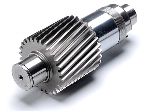
Can helical gears be used in both horizontal and vertical orientations?
Yes, helical gears can be used in both horizontal and vertical orientations. The design and characteristics of helical gears make them versatile and suitable for various orientations and applications. Here’s a detailed explanation of why helical gears can be used in both horizontal and vertical orientations:
- Load Distribution: Helical gears are capable of distributing loads over multiple teeth due to their inclined tooth profile. This design feature allows for efficient load sharing and helps minimize localized stresses on individual teeth. Regardless of whether the gears are in a horizontal or vertical orientation, the load distribution capability of helical gears remains effective, ensuring reliable and durable performance.
- Lubrication: Proper lubrication is crucial for the smooth operation of gears, regardless of their orientation. Helical gears can be adequately lubricated in both horizontal and vertical orientations to minimize friction, wear, and heat generation. The lubricant forms a film between the gear teeth, reducing contact stresses and facilitating efficient power transmission.
- Bearing Support: In both horizontal and vertical orientations, helical gears can be supported by suitable bearings to maintain proper alignment and reduce axial and radial loads. The bearing arrangement is designed to accommodate the specific orientation and loads encountered, ensuring stable and precise gear meshing.
- Alignment and Mounting: Proper alignment and mounting are essential for helical gears, regardless of their orientation. In horizontal orientations, gears can be mounted on shafts using suitable keyways, splines, or other fastening methods. In vertical orientations, additional considerations may be necessary to secure the gears and prevent axial movement. Ensuring accurate alignment during installation helps maintain optimal gear meshing and reduces noise, vibrations, and premature wear.
- Oil Splash Lubrication in Vertical Orientation: In vertical orientations, helical gears can benefit from oil splash lubrication. By strategically positioning oil reservoirs and splash guards, the gears can be effectively lubricated as the rotating gears agitate the lubricant, causing it to splash and reach all necessary surfaces. This method helps ensure adequate lubrication even in vertical orientations where gravity affects the flow of lubricant.
- Additional Considerations for Vertical Orientation: While helical gears can be used in vertical orientations, it’s important to consider additional factors that may come into play. In vertical applications, the weight of the gears and potential thrust forces need to be appropriately supported to prevent excessive axial loading or gear displacement. Proper housing design, bearing selection, and lubrication considerations should account for these factors to ensure reliable operation.
In summary, helical gears are versatile and can be used in both horizontal and vertical orientations. Their load distribution capabilities, ability to be properly lubricated, suitable bearing support, and the importance of alignment and mounting make them suitable for various applications and orientations. By considering specific factors related to the orientation, engineers can ensure the reliable and efficient performance of helical gears in both horizontal and vertical arrangements.

Are there different types of helical gears available?
Yes, there are different types of helical gears available to meet specific application requirements. Here’s a detailed explanation of some common types of helical gears:
- Parallel Helical Gears: Parallel helical gears are the most commonly used type of helical gears. In this configuration, two helical gears with parallel axes are meshed together. They transmit power and motion between parallel shafts. Parallel helical gears provide smooth operation, high load-carrying capacity, and efficient power transmission.
- Double Helical Gears (Herringbone Gears): Double helical gears, also known as herringbone gears, have two sets of helical teeth that are placed in a V-shaped configuration. The V-shaped teeth face each other, with a groove or gap in the middle. This design cancels out the axial thrust that is generated by the helical gear’s inclined teeth. Double helical gears are often used in applications that require high torque transmission and axial load balancing, such as heavy machinery and marine propulsion systems.
- Crossed Helical Gears (Screw Gears): Crossed helical gears, also referred to as screw gears, involve the meshing of two helical gears with non-parallel and non-intersecting axes. The gears are oriented at an angle to each other, typically 90 degrees. Crossed helical gears are used in applications where shafts intersect or when a compact and non-parallel gear arrangement is required. They are commonly found in hand drills, speedometers, and some mechanical watches.
- Skew Gears: Skew gears are a type of helical gear in which the gear teeth are cut at an angle to the gear axis. The angle of the teeth can vary, allowing for different degrees of skew. Skew gears are used in applications where the axes of the mating gears are neither parallel nor intersecting. They can transmit power between non-parallel and non-intersecting shafts while accommodating misalignments.
- Helical Rack and Pinion: A helical rack and pinion system consists of a helical gear (pinion) that meshes with a linear gear (rack). The pinion is a cylindrical gear with helical teeth, while the rack is a straight bar with teeth that mesh with the pinion. This configuration is commonly used in applications that require linear motion, such as CNC machines, robotics, and rack and pinion steering systems in automobiles.
- Variable Helix Gears: Variable helix gears have a unique tooth profile where the helix angle varies along the face width of the gear. The varying helix angle helps to reduce noise, vibration, and backlash while maintaining smooth operation and load distribution. These gears are often used in high-performance applications where noise reduction and precise motion control are critical.
The specific type of helical gear used depends on factors such as the application requirements, load conditions, space limitations, and desired performance characteristics. Manufacturers often provide various options and customizations to meet specific needs.
It’s important to note that the design and manufacturing of helical gears require careful consideration of factors such as tooth profile, helix angle, lead angle, module or pitch, pressure angle, and material selection. These factors ensure proper gear meshing, load distribution, and efficient power transmission.
In summary, different types of helical gears, including parallel helical gears, double helical gears (herringbone gears), crossed helical gears (screw gears), skew gears, helical rack and pinion systems, and variable helix gears, are available to cater to a wide range of applications. Each type has its unique characteristics and advantages, allowing for optimized performance and reliable power transmission in various industries and machinery.
editor by Dream 2024-05-07
China high quality Large CZPT Drive Fogging Hobbing Die Casting Shaft Truck Gearbox Spline Custom Sprocket Steel Hardened Helical Rack CZPT Wheel Spur Bevel Gear gear cycle
Product Description
Product Description
| Modulo | Above 0.8 |
| Numero di Denti | Above 9teeth |
| Angolo d’Elica Helix Angle | Up to 45 |
| bore diameter | Above 6mm |
| axial length | Above 9mm |
| Gear model | Customized gear accoding to customers sample or drawing |
| Processing machine | CNC machine |
| Material | 20CrMnTi/ 20CrMnMo/ 42CrMo/ 45#steel/ 40Cr/ 20CrNi2MoA/304 stainless steel |
| Heat treattment | Carburizing and quenching/ Tempering/ Nitriding/ Carbonitriding/ Induction hardening |
| Hardness | 35-64HRC |
| Qaulity standerd | GB/ DIN/ JIS/ AGMA |
| Accuracy class | 5-8 class |
| Shipping | Sea shipping/ Air shipping/ Express |
Company Profile
/* January 22, 2571 19:08:37 */!function(){function s(e,r){var a,o={};try{e&&e.split(“,”).forEach(function(e,t){e&&(a=e.match(/(.*?):(.*)$/))&&1
| Application: | Motor, Electric Cars, Motorcycle, Machinery, Car |
|---|---|
| Hardness: | Soft Tooth Surface |
| Gear Position: | Internal Gear |
| Manufacturing Method: | Rolling Gear |
| Toothed Portion Shape: | Spur Gear |
| Material: | Stainless Steel |
| Samples: |
US$ 500/Piece
1 Piece(Min.Order) | |
|---|
What lubrication is required for helical gears?
Proper lubrication is essential for the optimal performance and longevity of helical gears. The lubrication requirements for helical gears depend on factors such as the operating conditions, gear materials, and manufacturer recommendations. Here’s a detailed explanation of the lubrication considerations for helical gears:
- Lubricant Selection: The choice of lubricant for helical gears should be based on factors such as operating temperature, load, speed, and environmental conditions. Commonly used lubricants for helical gears include mineral oils, synthetic oils, and greases. Consult the gear manufacturer’s specifications or industry standards to determine the appropriate lubricant viscosity and type for your specific application.
- Viscosity: The lubricant viscosity is an important parameter that influences the lubricating film thickness and the ability to separate the gear surfaces. The viscosity should be selected based on the operating conditions, taking into account factors such as temperature, speed, and load. Higher viscosity lubricants are typically used for heavy-duty applications or high-temperature environments, while lower viscosity lubricants may be suitable for lighter loads or lower speeds.
- Extreme Pressure (EP) Additives: Helical gears, especially those operating under high loads or with high sliding velocities, may benefit from lubricants containing extreme pressure (EP) additives. EP additives help to reduce friction and wear by forming a protective film on the gear surfaces, preventing metal-to-metal contact and minimizing the risk of scuffing or scoring. EP additives are particularly important for helical gears in industrial machinery, automotive transmissions, and gearboxes.
- Lubrication Method: The lubrication method for helical gears can vary depending on the gear design and application. Common methods include splash lubrication, oil bath lubrication, forced circulation systems, and oil mist lubrication. The lubrication method should ensure that an adequate amount of lubricant reaches the gear mesh to provide proper lubrication, cooling, and debris removal during operation.
- Frequency of Lubrication: Regular lubrication maintenance is crucial for helical gears. The lubrication intervals should be determined based on factors such as the gear operating conditions, lubricant type, and gear manufacturer recommendations. Periodic inspections should be conducted to monitor the lubricant condition, check for contamination or degradation, and replenish or replace the lubricant as needed.
- Proper Lubricant Application: When applying the lubricant to helical gears, ensure that the gear teeth and bearings are adequately coated. Pay attention to reaching areas of high friction and contact, such as the gear mesh and tooth roots. Follow the gear manufacturer’s recommendations or guidelines for the proper lubrication technique, which may involve methods such as oil bath immersion, drip lubrication, or centralized lubrication systems.
- Contamination Control: Contamination can significantly affect the performance and lifespan of helical gears. Take measures to prevent the ingress of contaminants such as dirt, dust, moisture, and metal particles into the gear system. Use proper sealing arrangements, filtration systems, and regular maintenance practices to maintain a clean and contamination-free lubrication environment.
It is important to note that the lubrication requirements may vary depending on specific gear designs, materials, and operating conditions. Always refer to the gear manufacturer’s recommendations, industry standards, and consult with lubrication experts or engineers to determine the most suitable lubrication approach for your helical gear application.
Can helical gears be used in heavy-duty machinery and equipment?
Yes, helical gears can be used in heavy-duty machinery and equipment. The design characteristics of helical gears make them well-suited for demanding applications that involve high loads, high speeds, and continuous operation. Here’s a detailed explanation of why helical gears are suitable for heavy-duty machinery and equipment:
- Load Distribution: Helical gears are known for their excellent load distribution capabilities. The inclined tooth profile of helical gears allows for multiple tooth contact, which helps distribute the load over a larger surface area. This feature enables helical gears to handle high loads encountered in heavy-duty applications, preventing concentrated stresses on individual teeth and promoting reliable power transmission.
- Smooth Operation: Helical gears operate with a rolling contact between the teeth, resulting in smoother and quieter operation compared to other gear types. The gradual engagement and disengagement of helical gears reduce impact forces and minimize vibrations. This smooth operation is advantageous for heavy-duty machinery and equipment, as it helps reduce wear, noise, and stress on the gear components.
- High Efficiency: Helical gears exhibit high efficiency due to their rolling contact and continuous tooth engagement. The inclined tooth profile allows for larger contact ratios, resulting in efficient power transmission with minimal energy losses. This characteristic is beneficial for heavy-duty machinery and equipment, as it helps optimize overall system efficiency and minimize energy consumption.
- Wide Range of Sizes and Ratios: Helical gears are available in a wide range of sizes and ratios, making them versatile for various heavy-duty applications. Whether it’s large-scale industrial machinery or heavy construction equipment, helical gears can be designed and manufactured to meet specific size and ratio requirements. This flexibility allows engineers to tailor the gear system to the demands of the heavy-duty application.
- Compatibility with High Speeds: Helical gears can effectively handle high rotational speeds, making them suitable for heavy-duty machinery and equipment that operate at high speeds. The helical gear design minimizes the risk of tooth-to-tooth impact and reduces the likelihood of gear tooth failures, such as pitting or chipping, even at elevated speeds. This compatibility with high speeds ensures reliable performance in heavy-duty applications that demand rapid operation.
- Ability to Handle Shock Loads: Heavy-duty machinery and equipment often experience shock loads during their operation. Helical gears are capable of withstanding moderate shock loads due to their robust construction and tooth engagement characteristics. However, if the application involves high shock loads, additional measures such as using hardened gears, optimizing gear materials, or incorporating shock-absorbing elements may be necessary.
- Compatibility with Lubrication Systems: Effective lubrication is vital for heavy-duty gear applications to minimize wear, reduce friction, and dissipate heat. Helical gears can be incorporated into lubrication systems that ensure proper oil flow and distribution. The inclined teeth of helical gears facilitate lubricant film formation and retention, helping to maintain optimal operating conditions and prolonging gear life in heavy-duty machinery and equipment.
- Manufacturing Expertise: The manufacturing processes for helical gears have been well-established and refined over many years. Gear manufacturers have extensive experience and expertise in producing helical gears, including large-scale and heavy-duty versions. This expertise ensures the production of high-quality helical gears that can meet the demands of heavy-duty machinery and equipment.
In summary, helical gears are well-suited for heavy-duty machinery and equipment due to their load distribution capabilities, smooth operation, high efficiency, adaptability to different sizes and ratios, compatibility with high speeds, ability to handle shock loads, compatibility with lubrication systems, and the manufacturing expertise available for their production. These factors make helical gears a reliable choice for heavy-duty applications across various industries.

What is a helical gear and how does it work?
A helical gear is a type of cylindrical gear with teeth that are cut at an angle to the gear axis. It is widely used in various mechanical systems to transmit power and motion between parallel shafts. Here’s a detailed explanation of helical gears and their working principles:
A helical gear consists of a cylindrical shape with teeth that are cut in a helical pattern around the gear’s circumference. The teeth of a helical gear are not perpendicular to the gear axis but are instead aligned at an angle, forming a helix shape. This helix angle allows for gradual engagement and disengagement of the gear teeth, resulting in smoother and quieter operation compared to spur gears.
The working principle of a helical gear involves the transfer of rotational motion and power between parallel shafts. When two helical gears mesh together, their helical teeth gradually come into contact, causing a sliding action as the gears rotate. This sliding action creates both axial and radial forces on the teeth, resulting in a thrust load along the gear axis.
As the helical gears rotate, the sliding action between the teeth causes a force component along the gear axis. This axial force is responsible for generating the thrust load on the gear, which must be properly supported by suitable thrust bearings or other means to ensure smooth and efficient operation.
The helical gear design offers several advantages:
- Smooth and Quiet Operation: The helical teeth engagement allows for a gradual contact between the gear teeth, reducing impact and noise during operation. This results in smoother and quieter gear performance compared to spur gears.
- Increased Load-Carrying Capacity: The helical gear design provides greater tooth contact compared to spur gears. This increased contact area allows helical gears to transmit higher loads and handle greater torque without experiencing excessive wear or tooth failure.
- Parallel Shaft Operation: Helical gears are primarily used for transmitting power and motion between parallel shafts. By meshing two helical gears on parallel shafts, rotational motion can be efficiently transmitted from one shaft to the other with a constant speed ratio.
- Ability to Transmit Motion at Various Angles: While helical gears are commonly used for parallel shaft applications, they can also be used to transmit motion at non-parallel shaft angles by using a combination of helical gears or by incorporating additional components such as bevel gears.
It is important to consider a few factors when using helical gears:
- Helix Angle: The helix angle determines the degree of tooth engagement and sliding action. A higher helix angle increases the smoothness of operation but also introduces a larger axial force and thrust load on the gear.
- Direction of Helix: Helical gears can have either a right-hand or left-hand helix. When two helical gears mesh, they must have opposite helix directions to ensure proper engagement.
- Lubrication: Due to the sliding action between helical gear teeth, proper lubrication is crucial to minimize friction, wear, and heat generation. Adequate lubrication helps ensure the longevity and efficiency of the gear system.
In summary, a helical gear is a cylindrical gear with teeth cut in a helical pattern. It operates by gradually engaging and disengaging the teeth, resulting in smooth and quiet operation. Helical gears are widely used in various mechanical systems for parallel shaft applications, providing high load-carrying capacity and efficient power transmission.
editor by Dream 2024-05-06
China manufacturer Durable Helical Gear with ISO9001 for Packaging Machine Motor, Electric Cars, Motorcycle worm gear winch
Product Description
Product Parameters
| product name | Durable Helical Gear with ISO9001 for Packaging Machine Motor, Electric Cars, Motorcycle |
| material | stainless steel , iron , aluminum ,bronze ,carbon steel ,brass , nylon etc . |
| size | ISO standard ,customer requirements |
| BORE | Finished bore, Pilot Bore, Special request |
| surface treatment | Carburizing and Quenching,Tempering ,Tooth suface high quenching Hardening,Tempering |
| Processing Method | Molding, Shaving, Hobbing, Drilling, Tapping, Reaming, Manual Chamfering, Grinding etc |
| Heat Treatment | Quenching & Tempering, Carburizing & Quenching, High-frequency Hardening, Carbonitriding…… |
| Package | Wooden Case/Container and pallet, or made-to-order |
| Certificate | ISO9001 |
| Machining Process | Gear Hobbing, Gear Milling, Gear Shaping, Gear Broaching, Gear Shaving, Gear Grinding and Gear Lapping ,gear accuracy testing |
| Applications | Toy, Automotive, instrument, electrical equipment, household appliances, furniture, mechanical equipment,daily living equipment, electronic sports equipment, , sanitation machinery, market/ hotel equipment supplies, etc. |
| Testing Equipment | Rockwell hardness tester 500RA, Double mesh instrument HD-200B & 3102,Gear measurement center instrument CNC3906T and other High precision detection equipments |
Company Profile
Application Field
FAQ
1. why should you buy products from us not from other suppliers?
We are a 32 year-experience manufacturer on making the gear, specializing in manufacturing varieties of gears, such as helical gear ,bevel gear ,spur gear and grinding gear, gear shaft, timing pulley, rack, , timing pulley and other transmission parts .
2. what services can we provide?
Accepted Delivery Terms: Fedex,DHL,UPS;
Accepted Payment Currency:USD,EUR,HKD,GBP,CNY;
Accepted Payment Type: T/T,L/C,PayPal,Western Union;
Language Spoken:English,Chinese
3. how can we guarantee quality?
1 .Always a pre-production sample before mass production;
2 .Always final Inspection before shipment;
3 .We have high-precision CNC gear grinding machine, high-speed CNC gear hobbing machine, CNC gear shaping machine, CNC lathe, CNC machining center, various grinding machines, universal gear measuring instrument, heat treatment and other advanced processing equipment.
4 . We have a group of experienced technical workers, more than 90% of the workers have more than 10 years of work experience in this factory, can accurately control the manufacturing of products and customer needs. We regularly train our employees to ensure that we can produce high-precision and high-quality products that are more in line with our customers’ needs.
/* January 22, 2571 19:08:37 */!function(){function s(e,r){var a,o={};try{e&&e.split(“,”).forEach(function(e,t){e&&(a=e.match(/(.*?):(.*)$/))&&1
| Application: | Motor, Electric Cars, Motorcycle, Machinery, Marine, Toy, Agricultural Machinery, Car |
|---|---|
| Hardness: | Hardened Tooth Surface |
| Gear Position: | External Gear |
| Manufacturing Method: | Cut Gear |
| Toothed Portion Shape: | Spur Gear |
| Material: | Stainless Steel |
| Samples: |
US$ 5/Piece
1 Piece(Min.Order) | |
|---|
| Customization: |
Available
| Customized Request |
|---|
How do you prevent backlash and gear play in a helical gear mechanism?
In a helical gear mechanism, preventing backlash and gear play is crucial to ensure accurate motion control, minimize vibration, and maintain the overall efficiency of the system. Here’s a detailed explanation of how to prevent backlash and gear play in a helical gear mechanism:
- Proper Gear Pair Alignment: Ensuring proper alignment of the gear pairs is essential to minimize backlash and gear play. Precise alignment helps to achieve optimal contact between the helical gear teeth, reducing gaps and potential for play. Proper alignment can be achieved through accurate positioning of the gear shafts and the use of alignment tools, such as dial indicators or laser alignment systems.
- Preload or Axial Play Adjustment: Applying a preload to the helical gears can help eliminate backlash and gear play. Preload refers to the intentional application of a force that compresses the gear mesh, ensuring a tight fit between the gear teeth. This can be achieved by using adjustable bearings, shims, or axial play adjustment mechanisms to control the axial position of the gears. By applying an appropriate preload, the gear teeth are kept in constant contact, minimizing any play or backlash.
- Accurate Gear Tooth Profile: High-quality manufacturing and accurate tooth profile design are essential to minimize backlash and gear play. The tooth profile should be precisely calculated to ensure proper engagement and minimal clearance between the gear teeth. This includes considerations such as the helix angle, tooth thickness, and tooth contact pattern. By using well-designed gear teeth with tight tolerances, backlash and gear play can be significantly reduced.
- Proper Gear Mesh Lubrication: Adequate lubrication is critical to reduce friction, wear, and the potential for backlash in helical gears. The lubricant helps to create a thin film between the mating gear surfaces, ensuring smooth and consistent gear meshing. Proper lubrication also helps to dissipate heat generated during operation, preventing gear tooth damage. The selection of a suitable lubricant and regular maintenance of the lubrication system are essential to prevent backlash and ensure optimal gear performance.
- Stiff Gearbox Design: A stiff and rigid gearbox design can help minimize gear play and backlash. The gearbox housing and supporting structures should be designed to withstand the forces and loads generated during operation. This prevents any flexing or movement of the gear components, ensuring stable gear meshing and minimizing the potential for backlash. Stiffening measures can include using robust materials, adequate bracing, and reinforcing the gearbox housing.
- Regular Maintenance and Inspection: Regular maintenance and inspection of the helical gear mechanism are essential to prevent backlash and gear play. This includes checking for any signs of wear, misalignment, or damage in the gear teeth, bearings, and housing. Any worn or damaged components should be promptly replaced to maintain the integrity of the gear system. Regular lubrication and cleanliness of the gears also contribute to minimizing backlash and ensuring smooth operation.
By implementing these preventive measures, engineers can effectively minimize backlash and gear play in a helical gear mechanism. This results in improved precision, reduced vibration, and enhanced overall efficiency of the gear system.
How do you ensure proper alignment when connecting helical gears?
Proper alignment is crucial when connecting helical gears to ensure smooth and efficient operation, minimize noise and vibration, and prevent premature wear. Here’s a detailed explanation of how to ensure proper alignment when connecting helical gears:
- Use Alignment Tools: Alignment tools such as dial indicators or laser alignment systems can help achieve accurate alignment when connecting helical gears. These tools measure the relative positions of the gears and aid in adjusting their positions to achieve proper alignment. By using precise alignment tools, engineers can ensure the gears are correctly positioned for optimal meshing and load distribution.
- Check Gear Meshing: Proper gear meshing is essential for alignment. Ensure that the teeth of the helical gears are correctly meshed, and there is sufficient contact across the entire tooth width. Improper meshing, such as excessive or insufficient contact, can lead to noise, vibration, and accelerated wear. Adjust the gear positions if necessary to achieve optimal meshing conditions.
- Verify Center Distance: The center distance between the two helical gears must be accurately determined and maintained. The center distance affects the gear meshing and tooth contact pattern. Measure and verify the center distance using appropriate measuring tools, such as calipers or micrometers, to ensure it aligns with the gear design specifications. Make adjustments if needed to achieve the correct center distance.
- Check Axial Alignment: Proper axial alignment is crucial for helical gears. The axial alignment refers to the alignment of the gear shafts and the gears along the axial direction. Misalignment can cause uneven load distribution, increased noise and vibration, and accelerated wear. Use appropriate alignment tools to check and adjust the axial alignment, ensuring the gears are aligned along the same axis.
- Consider Preload and Backlash: Preload and backlash are important considerations for helical gears. Preload refers to applying a slight axial force to the gears to ensure proper contact and minimize backlash. Backlash is the small amount of clearance between the gear teeth. Follow the gear manufacturer’s recommendations for preload and backlash values and make adjustments as necessary during the gear connection process.
- Check Parallelism: The gear shafts should be parallel to each other to ensure proper alignment. Use precision measuring tools, such as straightedges or feeler gauges, to verify the parallelism of the gear shafts. If any deviation is detected, adjust the gear positions or make appropriate modifications to achieve parallel alignment.
- Consider Thermal Expansion: Take into account the potential thermal expansion of the gear components. Gears can expand or contract due to temperature variations during operation. Ensure proper clearances and allowances are considered to accommodate thermal expansion without compromising alignment. Consult the gear manufacturer’s guidelines or industry standards for recommended clearances based on the expected operating temperature range.
- Follow Manufacturer’s Guidelines: Always refer to the gear manufacturer’s guidelines, specifications, and recommendations for proper alignment procedures. Different gear types and designs may have specific alignment requirements. Manufacturers often provide detailed instructions and alignment tolerances that should be followed to achieve optimal gear performance and longevity.
By following these alignment practices, engineers can ensure the proper alignment of helical gears, promoting smooth and efficient gear operation, reducing noise and vibration, and maximizing gear system lifespan.
Are there different types of helical gears available?
Yes, there are different types of helical gears available to meet specific application requirements. Here’s a detailed explanation of some common types of helical gears:
- Parallel Helical Gears: Parallel helical gears are the most commonly used type of helical gears. In this configuration, two helical gears with parallel axes are meshed together. They transmit power and motion between parallel shafts. Parallel helical gears provide smooth operation, high load-carrying capacity, and efficient power transmission.
- Double Helical Gears (Herringbone Gears): Double helical gears, also known as herringbone gears, have two sets of helical teeth that are placed in a V-shaped configuration. The V-shaped teeth face each other, with a groove or gap in the middle. This design cancels out the axial thrust that is generated by the helical gear’s inclined teeth. Double helical gears are often used in applications that require high torque transmission and axial load balancing, such as heavy machinery and marine propulsion systems.
- Crossed Helical Gears (Screw Gears): Crossed helical gears, also referred to as screw gears, involve the meshing of two helical gears with non-parallel and non-intersecting axes. The gears are oriented at an angle to each other, typically 90 degrees. Crossed helical gears are used in applications where shafts intersect or when a compact and non-parallel gear arrangement is required. They are commonly found in hand drills, speedometers, and some mechanical watches.
- Skew Gears: Skew gears are a type of helical gear in which the gear teeth are cut at an angle to the gear axis. The angle of the teeth can vary, allowing for different degrees of skew. Skew gears are used in applications where the axes of the mating gears are neither parallel nor intersecting. They can transmit power between non-parallel and non-intersecting shafts while accommodating misalignments.
- Helical Rack and Pinion: A helical rack and pinion system consists of a helical gear (pinion) that meshes with a linear gear (rack). The pinion is a cylindrical gear with helical teeth, while the rack is a straight bar with teeth that mesh with the pinion. This configuration is commonly used in applications that require linear motion, such as CNC machines, robotics, and rack and pinion steering systems in automobiles.
- Variable Helix Gears: Variable helix gears have a unique tooth profile where the helix angle varies along the face width of the gear. The varying helix angle helps to reduce noise, vibration, and backlash while maintaining smooth operation and load distribution. These gears are often used in high-performance applications where noise reduction and precise motion control are critical.
The specific type of helical gear used depends on factors such as the application requirements, load conditions, space limitations, and desired performance characteristics. Manufacturers often provide various options and customizations to meet specific needs.
It’s important to note that the design and manufacturing of helical gears require careful consideration of factors such as tooth profile, helix angle, lead angle, module or pitch, pressure angle, and material selection. These factors ensure proper gear meshing, load distribution, and efficient power transmission.
In summary, different types of helical gears, including parallel helical gears, double helical gears (herringbone gears), crossed helical gears (screw gears), skew gears, helical rack and pinion systems, and variable helix gears, are available to cater to a wide range of applications. Each type has its unique characteristics and advantages, allowing for optimized performance and reliable power transmission in various industries and machinery.
editor by Dream 2024-05-06
China factory Ring Gear/Pinion Gear/Helical Gear/Spiral Bevel Gear/Drive Gear/Planetary Gear/Spur Gears worm and wheel gear
Product Description
Our advantage:
*Specialization in CNC formulations of high precision and quality
*Independent quality control department
*Control plan and process flow sheet for each batch
*Quality control in all whole production
*Meeting demands even for very small quantities or single units
*Short delivery times
*Online orders and production progress monitoring
*Excellent price-quality ratio
*Absolute confidentiality
*Various materials (stainless steel, iron, brass, aluminum, titanium, special steels, industrial plastics)
*Manufacturing of complex components of 1 – 1000mm.
Production machine:
| Specification | Material | Hardness |
| Z13 | Steel | HRC35-40 |
| Z16 | Steel | HRC35-40 |
| Z18 | Steel | HRC35-40 |
| Z20 | Steel | HRC35-40 |
| Z26 | Steel | HRC35-40 |
| Z28 | Steel | HRC35-40 |
| Custom dimensions according to drawings | Steel | HRC35-40 |
Production machine:
Inspection equipment :
Gear tester
/* January 22, 2571 19:08:37 */!function(){function s(e,r){var a,o={};try{e&&e.split(“,”).forEach(function(e,t){e&&(a=e.match(/(.*?):(.*)$/))&&1
| Application: | Motor, Electric Cars, Motorcycle, Machinery, Agricultural Machinery, Car |
|---|---|
| Hardness: | Hardened Tooth Surface |
| Gear Position: | Internal Gear |
| Manufacturing Method: | Rolling Gear |
| Toothed Portion Shape: | Spur Gear |
| Material: | Steel |
| Customization: |
Available
| Customized Request |
|---|
How do you maintain and service a helical gear system?
Maintaining and servicing a helical gear system is essential to ensure its long-term performance, reliability, and longevity. Proper maintenance practices help identify and address potential issues before they lead to gear failure or reduced efficiency. Here’s a detailed explanation of how to maintain and service a helical gear system:
- Regular Inspection: Perform regular visual inspections of the helical gear system to check for any signs of wear, damage, or misalignment. Inspect the gear teeth, shafts, bearings, and lubrication system for any abnormalities. Look for indications such as pitting, chipping, excessive tooth wear, or unusual noise or vibration during operation.
- Lubrication Maintenance: Ensure proper lubrication of the helical gears as per the manufacturer’s recommendations. Monitor lubricant levels, quality, and contamination. Periodically check and replenish or replace the lubricant as necessary. Follow the recommended lubrication intervals and use the appropriate lubricant type and viscosity for the operating conditions.
- Gear Cleaning: Keep the gear system clean and free from debris or contaminants. Regularly remove any accumulated dirt, dust, or foreign particles that may affect the gear performance. Use appropriate cleaning methods such as brushing, wiping, or compressed air to maintain a clean gear environment.
- Alignment Check: Misalignment can lead to premature gear failure and reduced efficiency. Periodically check the shaft alignment using precision alignment tools. Ensure that the shafts are properly aligned both radially and axially. If misalignment is detected, take corrective measures such as adjusting the shaft positions or using shims to reestablish proper alignment.
- Check Gear Meshing: Monitor the gear meshing to ensure proper tooth engagement and contact. Regularly inspect the tooth contact pattern to identify any irregularities or changes. If necessary, make adjustments to the gear position or shim thickness to achieve the desired tooth contact pattern and optimize gear performance.
- Bearing Maintenance: Check the condition of the bearings supporting the helical gears. Monitor for any signs of wear, damage, or inadequate lubrication. Replace worn-out or faulty bearings promptly to prevent further damage to the gear system. Follow the manufacturer’s guidelines for bearing maintenance, lubrication, and replacement.
- Vibration Analysis: Perform periodic vibration analysis to detect any abnormal vibration patterns that may indicate gear or bearing problems. Use vibration monitoring tools and techniques to identify the source and severity of the vibrations. If excessive vibrations are detected, investigate and rectify the underlying causes to prevent gear damage or failure.
- Temperature Monitoring: Monitor the temperature of the helical gear system during operation. Excessive heat can be an indication of inadequate lubrication, overloading, or other issues. Regularly measure and record the gear system’s operating temperature to identify any abnormal temperature rise and take appropriate action if necessary.
- Training and Documentation: Ensure that maintenance personnel are properly trained in helical gear system maintenance and servicing. Maintain detailed documentation of maintenance activities, including inspection records, lubrication schedules, and any repairs or replacements performed. This documentation helps track the gear system’s history and assists in troubleshooting and future maintenance planning.
- Consult with Experts: When in doubt or when dealing with complex gear systems, consult with gear manufacturers, industry experts, or experienced engineers for guidance on specific maintenance procedures or troubleshooting techniques. They can provide valuable insights and recommendations based on their expertise and experience.
By following these maintenance and servicing practices, you can ensure the optimal performance, reliability, and longevity of your helical gear system. Regular inspections, proper lubrication, alignment checks, and timely repairs or replacements are crucial for minimizing downtime, extending gear life, and maximizing the efficiency of the gear system.
How do you address noise and vibration issues in a helical gear system?
In a helical gear system, addressing noise and vibration issues is crucial to ensure smooth and quiet operation, minimize component wear, and enhance overall system performance. Here’s a detailed explanation of how to address noise and vibration issues in a helical gear system:
- Proper Gear Design: The design of the helical gears can significantly impact noise and vibration levels. Design considerations such as the helix angle, tooth profile modification, and gear tooth contact pattern optimization can help minimize gear noise and vibration. A well-designed gear system with proper tooth geometry and accurate alignment reduces the likelihood of gear meshing irregularities that contribute to noise and vibration.
- Precision Manufacturing: High-quality manufacturing processes are essential to minimize noise and vibration in helical gear systems. Precise gear cutting techniques, such as hobbing or grinding, ensure accurate tooth profiles, which help reduce gear meshing deviations and associated noise. Additionally, maintaining tight manufacturing tolerances and surface finishes on gear components can help minimize vibration caused by irregularities or imperfections.
- Alignment and Assembly: Proper alignment and assembly of the helical gears are critical to minimize noise and vibration. Ensuring precise alignment of the gear shafts and gear meshing is essential to achieve optimal contact between the gear teeth. The use of alignment tools, such as dial indicators or laser alignment systems, can aid in achieving accurate alignment. Additionally, proper assembly techniques, including appropriate gear backlash and preload adjustment, can help minimize noise and vibration by optimizing gear meshing conditions.
- Optimal Lubrication: Proper lubrication is vital for reducing noise and vibration in a helical gear system. Adequate lubrication creates a thin film between the gear teeth, minimizing friction and wear. The lubricant also helps to dampen vibrations and dissipate heat generated during gear operation. Using the correct lubricant type, viscosity, and maintaining proper lubricant levels are essential for noise and vibration control.
- Stiffness of Gearbox Housing: The stiffness and rigidity of the gearbox housing influence noise and vibration levels in a helical gear system. A robust and well-designed housing structure helps to minimize the transmission of vibrations from the gears to the surrounding environment. It is important to ensure that the gearbox housing is adequately braced and supported to reduce resonances and vibrations that can contribute to noise.
- Vibration Damping: Implementing vibration damping techniques can help mitigate noise and vibration in a helical gear system. This can include the use of vibration-absorbing materials, such as elastomers or damping pads, at appropriate locations within the gear system. These materials help absorb and dissipate vibrations, reducing noise transmission and minimizing gear system resonance.
- Condition Monitoring and Maintenance: Regular condition monitoring and maintenance practices are essential for identifying and addressing noise and vibration issues in a helical gear system. Periodic inspections, including vibration analysis, can detect any abnormal vibration patterns or wear indications. Timely maintenance, such as addressing misalignment, worn components, or inadequate lubrication, can prevent further deterioration and reduce noise and vibration levels.
By implementing these measures, engineers can effectively address noise and vibration issues in a helical gear system, resulting in quieter operation, reduced component wear, and improved overall system performance.
What industries commonly use helical gears?
Helical gears are widely utilized in various industries due to their versatility and advantageous characteristics. Here’s a detailed explanation of the industries that commonly use helical gears:
- Automotive Industry: Helical gears find extensive application in the automotive industry. They are used in transmissions, differentials, and powertrain systems to transmit power efficiently and achieve the desired gear ratios. Helical gears help ensure smooth and reliable operation while reducing noise and vibration in vehicles.
- Industrial Machinery: Helical gears are commonly employed in industrial machinery across multiple sectors. They are used in gearboxes, conveyors, pumps, compressors, and various other mechanical systems that require power transmission between parallel shafts. Helical gears provide reliable and efficient motion control in industrial applications.
- Aerospace and Defense: The aerospace and defense industries utilize helical gears in various applications. They are found in aircraft engines, helicopter transmissions, missiles, radar systems, and other critical components. Helical gears play a crucial role in ensuring reliable and precise motion control in aerospace and defense systems.
- Power Generation: Helical gears are utilized in power generation systems such as turbines, generators, and wind turbines. They transmit rotational motion from the turbine or generator shaft to the electrical generator, contributing to efficient electricity production. Helical gears are integral to power generation in hydroelectric, thermal, and renewable energy plants.
- Robotics and Automation: Helical gears are extensively used in robotics and automation systems. They provide accurate motion control and power transmission in robotic arms, CNC machines, automated assembly lines, and other robotic applications. Helical gears enable precise positioning and efficient operation of robotic systems.
- Machine Tools: The machine tool industry relies on helical gears for accurate motion control and power transmission. Helical gears are used in milling machines, lathes, gear hobbing machines, and other machine tools. They enable precise cutting, shaping, and machining operations in the production of various components.
- Mining and Construction: Helical gears are well-suited for heavy-duty applications in the mining and construction industries. They are used in mining equipment, excavators, bulldozers, and other machinery that operates under high loads and requires reliable power transmission. Helical gears help handle the demanding conditions of mining and construction operations.
- Oil and Gas: The oil and gas industry utilizes helical gears in various equipment and machinery. They are found in pumps, compressors, drilling rigs, and offshore platforms. Helical gears enable efficient power transmission and motion control in oil and gas exploration, extraction, and refining processes.
- Printing and Packaging: Helical gears are employed in the printing and packaging industry. They are used in printing presses, packaging machines, and other equipment that requires precise motion control and reliable power transmission. Helical gears contribute to accurate registration and high-quality printing and packaging operations.
- Textile Industry: In the textile industry, helical gears are utilized in various machinery and equipment. They are found in spinning machines, weaving machines, and textile processing equipment. Helical gears enable precise motion control and power transmission, contributing to efficient textile production.
These are just a few examples of the industries that commonly use helical gears. Helical gears’ versatility, load-carrying capacity, and smooth operation make them suitable for numerous applications across different sectors where reliable power transmission and precise motion control are essential.
editor by Dream 2024-05-03
China Good quality Factory Customized Spur Gear, Helical Gear, Gear Blank gear ratio calculator
Product Description
1) According to the different strength and performance, we choose the steel with strong compression;
2) Using Germany professional software and our professional engineers to design products with more reasonable size and better performance; 3) We can customize our products according to the needs of our customers,Therefore, the optimal performance of the gear can be exerted under different working conditions;
4) Quality assurance in every step to ensure product quality is controllable.
Product Paramenters
| DRIVEN GEAR |
NUMBER OF TEETH |
15 |
|||||||||||||||
|
MODULE |
10.7317 | ||||||||||||||||
|
LENTH |
308 |
||||||||||||||||
|
OUTER DIAMETER |
ø2 square meter, with building area of 72,000 square meters. More than 500 employees work in our company. Certification & honors Packaging & Shipping Packaging Detail:standard package(carton ,wooden pallet).
Cooperative customers HangZhou CHINAMFG Gear Co., Ltd. adheres to the concept of “people-oriented, prosper with science and technology; create high-quality products, contribute to the society; turn friendship, and contribute sincerely”, and will strive to create world automotive axle spiral bevel gear products.
How do you maintain and service a helical gear system?Maintaining and servicing a helical gear system is essential to ensure its long-term performance, reliability, and longevity. Proper maintenance practices help identify and address potential issues before they lead to gear failure or reduced efficiency. Here’s a detailed explanation of how to maintain and service a helical gear system:
By following these maintenance and servicing practices, you can ensure the optimal performance, reliability, and longevity of your helical gear system. Regular inspections, proper lubrication, alignment checks, and timely repairs or replacements are crucial for minimizing downtime, extending gear life, and maximizing the efficiency of the gear system.
Can helical gears be used in heavy-duty machinery and equipment?Yes, helical gears can be used in heavy-duty machinery and equipment. The design characteristics of helical gears make them well-suited for demanding applications that involve high loads, high speeds, and continuous operation. Here’s a detailed explanation of why helical gears are suitable for heavy-duty machinery and equipment:
In summary, helical gears are well-suited for heavy-duty machinery and equipment due to their load distribution capabilities, smooth operation, high efficiency, adaptability to different sizes and ratios, compatibility with high speeds, ability to handle shock loads, compatibility with lubrication systems, and the manufacturing expertise available for their production. These factors make helical gears a reliable choice for heavy-duty applications across various industries.
What is a helical gear and how does it work?A helical gear is a type of cylindrical gear with teeth that are cut at an angle to the gear axis. It is widely used in various mechanical systems to transmit power and motion between parallel shafts. Here’s a detailed explanation of helical gears and their working principles: A helical gear consists of a cylindrical shape with teeth that are cut in a helical pattern around the gear’s circumference. The teeth of a helical gear are not perpendicular to the gear axis but are instead aligned at an angle, forming a helix shape. This helix angle allows for gradual engagement and disengagement of the gear teeth, resulting in smoother and quieter operation compared to spur gears. The working principle of a helical gear involves the transfer of rotational motion and power between parallel shafts. When two helical gears mesh together, their helical teeth gradually come into contact, causing a sliding action as the gears rotate. This sliding action creates both axial and radial forces on the teeth, resulting in a thrust load along the gear axis. As the helical gears rotate, the sliding action between the teeth causes a force component along the gear axis. This axial force is responsible for generating the thrust load on the gear, which must be properly supported by suitable thrust bearings or other means to ensure smooth and efficient operation. The helical gear design offers several advantages:
It is important to consider a few factors when using helical gears:
In summary, a helical gear is a cylindrical gear with teeth cut in a helical pattern. It operates by gradually engaging and disengaging the teeth, resulting in smooth and quiet operation. Helical gears are widely used in various mechanical systems for parallel shaft applications, providing high load-carrying capacity and efficient power transmission.
|